DRG #168's Frame in HOn3, Part2
Metal, or plastic? Well, both…
Table of Contents:
So, this will not be the end-all of frame construction for #168. I just decided I’d figured and modeled enough to write a post, and I didn’t want to forget any of it…
Laws of physics tend to reveal themselves as one drags their best-laid designs out of the fantasy CAD world into the reality of actual parts. I knew going-in the frame was going to present such, and I’ve relied on the cheap, iterative workflow of 3D printing to expose them. Here, I’ll describe what I know so far, and how I’ve refactored the locomotive design to accommodate.
Modeling
(Top)
If you refer back to the previous frame post, you’ll see the frame developed as an end-to-end item, from the front bolster where the cowcatcher will be hung all the way back to the rear bolster that holds up the cab. And, all the way in between is resin plastic. Well, Mike Conder dragged me back to reality with a post in the HOn3 mailing list, pointing out that weight will be a significant factor in how much (if anything) the locomotive can pull. And, putting together the 3D printed assembliles really drove that home, for they in aggregate are extremely light.
Also, I started to expose what I suspected regarding 3D printing mechanical components, that there were printing limits to their resolution. To evaluate that, I added the crosshead guide hangar to the cylinder chest assembly, to print with standard resin. Here’s a picture where you can see what I got:
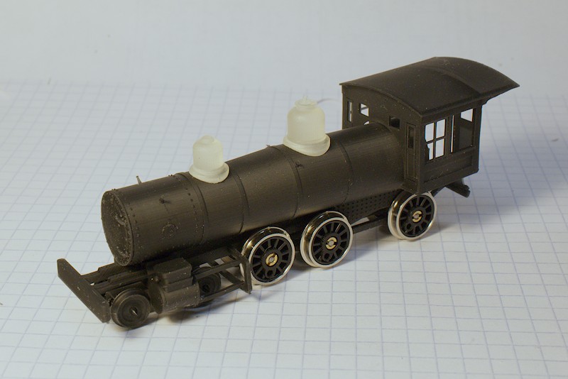
All the major assemblies loosely stacked together, so please ignore the out-of-square slop. Also, I included the Shapeways domes just for fun. But, look at the crosshead guide hangar, printed at 0.04" thickness as what I thought would be the minimum for mechanical integrity. Well, not only are they too soft to handle the back-and-forth of the crosshead, they just look too thick, model-like. I also printed the hangar/slide assembly at 0.02" in ABS-Like resin; a bit more dimensionally correct but too flimsy to survive wash/cure. So, this part gets relegated to brass, more on that in a bit.
But, the weight thing loomed large, and I started to see another refactor of the frame to accommodate. Thinking through it (the reason it’s been more than a month from the last frame post), I decided I wanted to accommodate options to a modeler in frame choice. The options gelled like this:
- Plastic, non-powered frame for a static model;
- Brass-printed, power-enabled frame, basically the plastic version brass-printed at Shapeways;
- Hand-crafted brass frame, for those so-inclined.
With all that thinking, plus considerations for mounting/attaching stuff, here’s what I have:
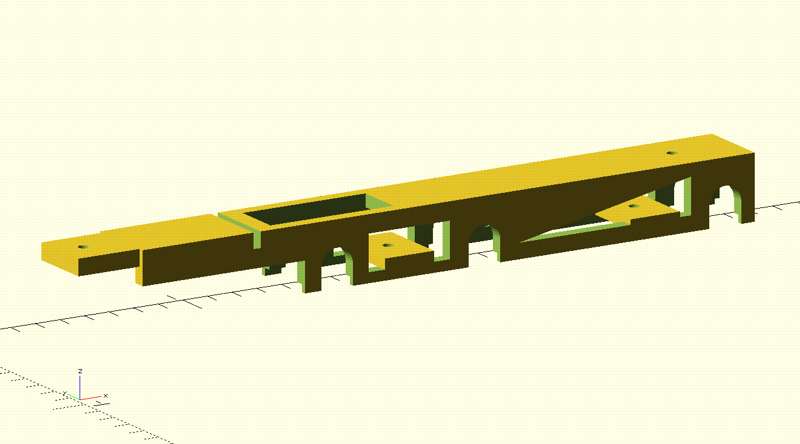
The big change was to remove the cylinder/chest assembly and everything forward. Now, that assembly has a slot in the back, into which the tab on the frame front will slide. The hole in the tab accommodates a 0-80 screw, which will hold the pilot truck, cylinder/chest (which I now call the frontend), frame, and smokebox together. The slot just behind the tab positions the valve gear hangar. The void behind that is for the gear on the front driver, but that’s not set in stone just yet. The two tabs/screwholes at the frame bottom are for holding a brass plate 0.02" thick that retains the drivers; note the inset notches in the frame sides' bottom for aligning it. And, the screw hole in the back is for attaching the firebox backhead and cab to the frame.
I also removed the frame backend, with the bolster and that cute little diagonal support member, and put that on the cab floor assembly.
Here’s a render of the stacked parts:
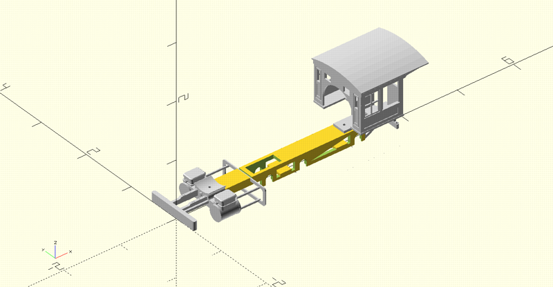
The nice thing about CAD is being able to lay this stuff out and see where the alignment goes. Particularly for the screw holes; I “drilled” each part with a subtraction of a cylinder the diameter of the 0-80 screw specification, about 0.06". To align them, I just put together the render above then sighted down each hole to see what didn’t align, using the frame as the reference. Anything that didn’t, I would just “scooch” the hole over a few thou at a time until it lined up. Right now, the remaining alignment to do is with the smokebox-boiler-firebox; it aligns based on sitting on the cylinder chest up front, and inserting over the firebox backhead in the rear. I think I still have some “scooching” to do at either end, probably more at the backhead; I also want to make a nice fit at the cab front wall.
I could have made “tap-able” screw holes in each of the smokebox and backhead as the top-most parts, to accommmodate the 0-80 screws. But instead, I decided to use metal nuts sitting in a retainer fixture modeled into the parts. The nuts will be held in these retainers with a drop of CA gel. Both of these parts require fine detail, and I didn’t think the required resin would be ammenable to holding a tapped screw.
With this design, the overall locomotive would assemble as follows: 1) attach the backhead to the cab tab with CA adhesive (I tried running the screw through all the loose pieces, no patience or fingers for it… :D ); 2) attach the cab/backhead assembly to the frame with a 0-80 screw; 3) slide the front end on the front frame tab; 4) slide the smokebox-boiler-firebox onto the backhead and lay on the cylinder chest; 5) finally, thread the screw through the pilot truck, through the frame and into the smokebox-boiler-firebox. What I’m counting on in this design is that the firebox will slide right over the motor-gearbox on its way to the backhead; we’ll see how that goes in a subsequent post.
The frame tab is something I tried to facilitate in all three frame options. Particularly for the hand-crafted frame, I decided to accommodate a standard part in the dimensions of the K&S Metals 1/4" wide by 0.064" thick brass strip, part #8245. So, the frame tab in the CAD model has those exact dimensions, 0.25" in length to stick in the cylinder chest far enough to cover the screw hole. In the cylinder chest model, I added a slot of the same dimensions plus 0.01 “slop”; tests of sliding a segment of the K&S material into the slot demonstrated a tight-but-accommodating fit.
Speaking of the hand-crafted frame, my thinking for it is an extension of the original laser-cut nickel frame. The design I have so far is what I’lll call a “butterfly” layout, where the two frame sides are laid out top-to-top, separated by a spacer:
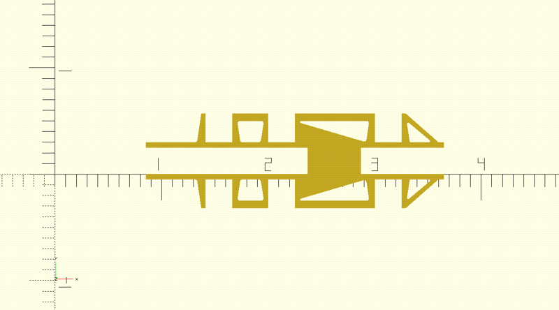
The frame would be cut out of 0.02" nickel-silver, and then bent into shape at the connecting tab. Then a segment of the K&S brass strip would be soldered in place in the front to provide the front end mounting tab. Note that this design is still a work-in-progress; it uses the ScaleLink hornblock bearings, and does not accommodate the cab attachment or bottom plate, yet. I probably won’t do anything further on it until after I get a full 3D printed article up and running.
Back to the 3D print, I think the current model will make a nice Shapeways brass casting. But for now, I’m going to do integration with a resin-printed version, in order to work out the kinks in part and propulsion integration. I dropped the frame into Shapeways' cart to cost it, about $26US. I may still have to add pieces, particularly to accommodate gear and motor mounting, so I don’t want to buy one just yet…
Fabrication
(Top)
I described a lot of my fabrication thinking in the previous section. So, here I’m going to concentrate on the resin-printed frame that’s going to proceed into construction of the first article, a non-powered model. Plus, I’m going to talk about some of the metal fabrication things I’m anticipating for the mechanical parts.
When I de-coupled the frame from the front-end, I did away with the need for printing detail with the frame. So now, printing orientation doesn’t matter as much, so I’m going back to my original horizontal print layout, with supports attached to the frame’s bottom. That will give a nice flat top to the frame. It’ll re-introduce some waviness in the slanted void between the main and rear drivers, but I’ll just support the c&*# out of it.
But now that I’ve printed the crosshead guide hangar and exposed its foils, I’ve re-introduced some metal work in the basic locomotive construction. Even for a static model, I’m not going to settle on “cartoon” parts.
I think there are somewhat distinct “levels” of metal work that are worth considering with regard to how far to invest in tools and skills. What I want to keep to in constructing this model is what I’ll call the “jeweler’s level”, using mostly hand- and some small powered-tools. Thing is, metal work requires a bit different thinking regarding the leverage the tools have over the material.
With wood, for instance, I could just mount the right-sized drill bit on the drill press and push it, rotating, through most wood and get a decent hole. Pay attention to which side you start on to leave the splintering to the “bad” side, and you’re good to go. Oh, not so with metal, particularly with brass. With regular drill bits, drilling holes in brass can be quite unsafe, as well as making crappy holes. To mitigate the behavior of the drill to “bite” the material, you need to file a small counter surface into the bit’s edges at the top; with that, the bite is mitigated and the bit performs more like it were drilling into wood. Geesh…
Cutting brass has similar considerations. This is particularly telling for the small parts needed for a HO locomotive’s valve gear and driver rods; I wish I could just buy 0.02" x 0.04" brass strip for the crosshead slides (well, I wasn’t able to find any). I did a lot of reading on how jewelers would do it, mainly involving a jeweler’s saw (small hacksaw with small-toothed blades) with the material resting on a “bench pin”, essentially a wood block with a “V” cut into it, a hole at the tip of the “V”. Cut shy of the line, then file to the line. Gee, with wood I used to make the line and cut right up to it with my table saw…
I did come across what appears to be a useful tool in brass cutting: a scroll saw. Model Railroader magazine’s “Build a brass steam locomotive” e-book by Stephen Anderson describes the utility of a powered scroll saw as follows: “Though not necessary, it can reduce an hour-long cutting job to about a minute.” Got my attention, and when my wife out of the blue sent me the Amazon link for such I jumped on it. What she found was the Dremel Moto-Saw MS-20, a kinda unique device in that it can operate as either a hand-held saw or a bench mounted one with the provided table fixture. With the limited testing I’ve done, it appears to be well-suited to the level of metal work I want to do here.
Looking at the model’s mechanical parts, I think most of them can be cut from 0.02" brass. That gets one out of the “lathe-mill” level of metal work, down to drill bits for the particularly sized holes, a small saw, and some sort of soldering device. Even then, if one wants to use a laser-cut concern like OSHCut, eliminate the saw. In that vein, I’m going to make sure all the parts I design will be fabricate-able with such a service.
So, the immediate task is to fabricate the crosshead guide hangar and slides. Here’s the CADed part:
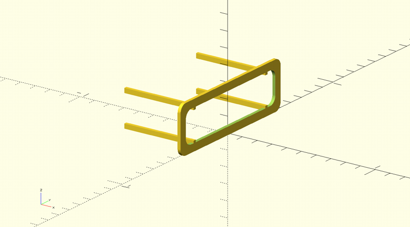
Now, for this post I’m not reporting results, just my tactical plan. Which is, the hangar and slides will be five parts, hangar, one each, slide, four each. All will be cut from 0.02" brass sheet. The hangar will start layed out as a rectangular piece of brass from which the inside will be cut out. Then, small slots to mount the sliders will be cut, then the whole piece will be cut from the sheet and the corners filed to curves. Assembly will be to solder the slides into the hangar slots, probably using some sort of fixture to hold things in place.
I’m going to write a separate post on fabricating and integrating the mechanical parts, so stay tuned…
Edit 2022-07-24: Changed “valve gear hangar” to “crosshead guide hangar”. Can’t just make it look prototypical, need to refer to it by the right name…