DRG #168 Decorations, Part 2
Does Amazon carry “CAD glue”?
Table of Contents:
In the Decorations Part 1 post, I was not happy with how the top-line parts attached to the smokebox-boiler-firebox. The convex curve of smokebox-boiler-firebox definitely did not match the concave curve of the same radius in the domes and stack. Okay, sanding of such is not rocket science, so I initially planned to print another batch and use sanding film wrapped around the base part to sand the concave curve of the topline part to fit.
But I got to thinking, these parts should print fine sitting on top of a 45-degree-tilted smokebox-boiler-firebox, effectively tilting 45 degrees in the opposite direction, requiring no supports. So, I set out to lay out a consoliated superstructure…
Modeling
(Top)
I really didn’t want to cut-paste code into a .scad file to do the consolitation. So I got to thinking, why not integrate the .stl files? I was already making “integration.scad” files of the for_print stl files as a second check of fit and alignment, could I not do the same to make a single printable part? Indeed, modeling this was trivial:
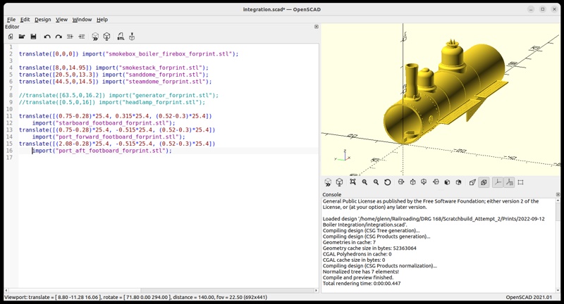
OpenSCAD’s import() operator is used to drag all the *_forprint.stl files into the modeling space. Using the smokebox-boiler-firebox as the anchor, I translated all the other parts to their correct positions. Note that I didn’t end up including the generator, bell and headlamp; these presented “island” edges that would require supports, and I preferred how I was supporting them when printed separately. I also included the footboards as I foresaw gluing them properly aligned to the superstructure to be a headache. I had to re-calculate part translations because I was now doing them in millimeters, rather than decimal inches when doing the same thing with the OpenSCAD modules.
The resuling model just looked a bit unwieldy to me, from the perspective of printing it. Here’s how that went…
Fabrication
(Top)
I made this one part a single print, as I didn’t want the distraction of handling other parts to make me miss something critical about this amalgam of parts. Turns out that was prescient…
Here’s the support strategy:
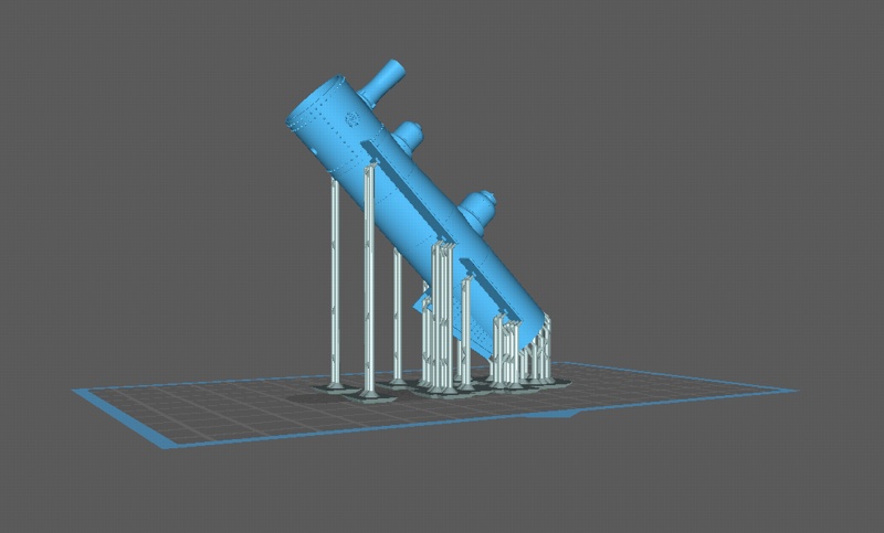
Previously, I printed the smokebox-boiler-firebox vertically, but I wasn’t liking the layer and pixel artifacts on the surface. To self-support the domes and stack they needed to be 45-degree-oriented, so I tilted the whole thing 45 degrees. Then, I went through the model and supported any edge that would “island” itself in the slicing. Simple enough, sliced it, saved the .ctb file, and took it to the printer. Here’s the result:
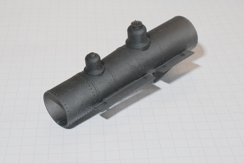
First things first, what’s missing? Yes, indeedy, there’s no smokestack. I thought, “Gee, I’m sure I uncommented the stack import() line in the .scad file…” so I double-checked and it was there. Also, it was there in the .ctb slice file. Hmmm, staring at the vat of resin, I surmised it’s gotta be in there somewhere, so I took the silicon spatula and dredged the goo. Sliding it on the bottom, it caught something on the FEP about where the stack would print, so now it was time to drain the vat and inspect that hang-up. And yep, there I found the the stack:
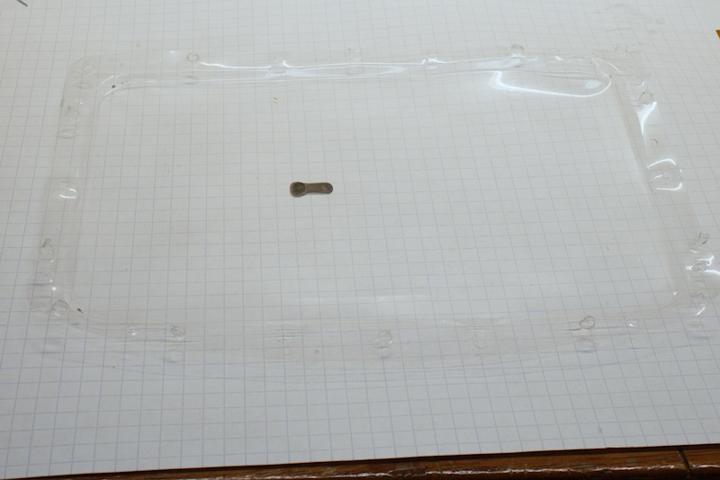
This is the FEP after removal from the vat. And there ’tis, a blob in the general shape of the smokestack. For some reason it chose to print itself without benefit of the build plate to pull it off the FEP, so it must not be attached to the rest of the model. Sure enough, inspecting the model in Chitubox revealed this:
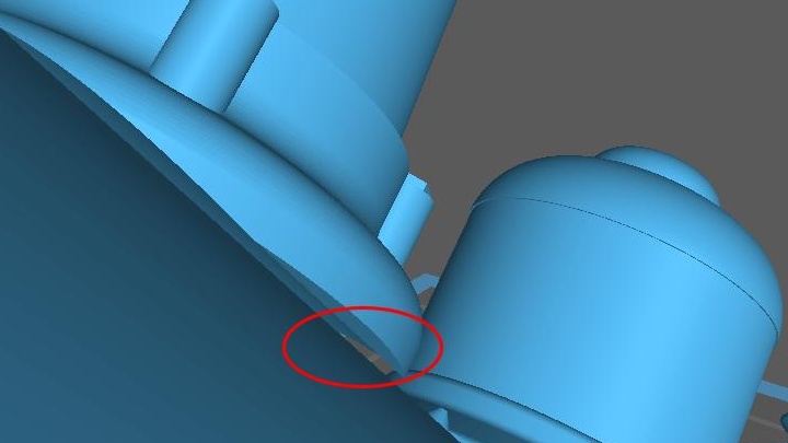
It is hard to see details in the CAD display renders, and the curved interface made it especially tough. So, when the layers including the stack were printed, they had no part attached to the rest of the model to pull them along. Here’s a look at one of the slices through the stack base:
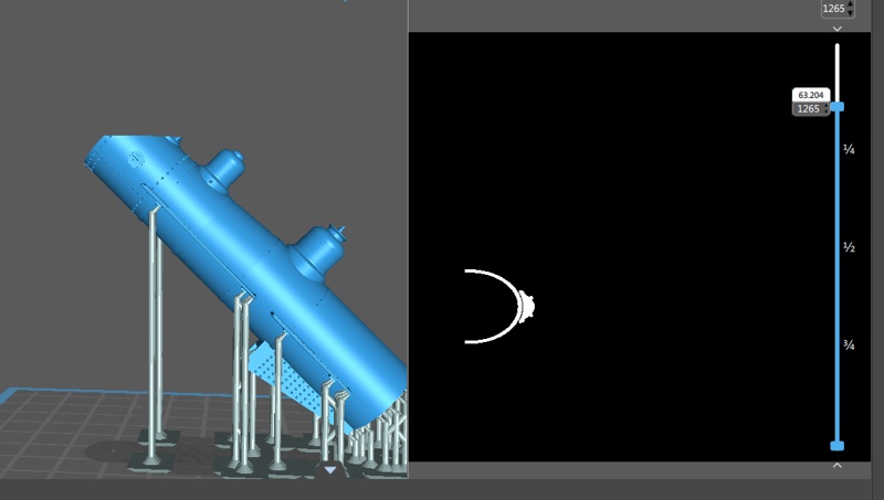
This is the slice screen of Chitubox. Note that I’ve pulled the slider on the right down to a layer containing the smokestack base, and the model render on the left is truncated at that layer. So, in the layer image (black-n-white window) note that the smokestack pixels are not attached to any part of the smokebox, and they started that way at the very first layer containing the stack. With neither some part of the model or dedicated supports to pull them along, the smokestack layers were just re-exposures of the first layer along with new exposure of the current layer. Hence, the “flat-stack” stuck to the FEP…
Not knowing how that affected the state of the FEP, I had to drain the vat (I was thinking it was about time to do that anyway, I’d done a bunch of prints with that resin in the vat). I also replaced the FEP as I wasn’t able to remove the stack without tools, although I later found that I could slide it around with my finger. I’m treating FEPs as a consumable, so I have about ten on hand, nine now. I drained the vat passing the resin through a filter, and a number of small pieces were filtered out. I prefer to keep my resins in vats, but that doesn’t abrogate the need to filter the resin once in a while.
On the model, I also noted some tearing and curving of the footboards. I increased their thickness from 0.02" to 0.03", and I added an additional mounting bracket for the long section. I’m also going to test printing them without supports; the farthest forward ones did not print with their supports for some reason, and they did just fine. I think they’re pulled along by the attachment to the superstructure.
The good news is that the domes attached quite nicely, with no unsightly glued seam. In fact, now they’re just part of the superstructure.
Ruminations
(Top)
So, this sort of integration isn’t reliant on OpenSCAD; it can be done in any CAD program that will import .stl files. What needs to happen to make it successful is for the parts to be “well-connected” to their adjacent parts. That means, no air between parts. For most parts, I insured that they were embedded a bit in the superstructure, on the theory that the slicer program would see it all as one part, layer-by-layer. The domes demonstrate this sort of integration very well, and the smokestack poigiantly demonstrates the implications of not getting the part well-embedded.
I was a bit worried that OpenSCAD wouldn’t export a .stl made up of .stls, but in the end it did that quite nicely. I did have to upgrade my OpenSCAD program to the master branch because the released version wasn’t doing the display rendering well. Both did the export render just fine, and the master branch version did it an order of magnitude faster owing to the recent work on render peformance. I had to compile the OpenSCAD source code to get that version, but it was worth the effort.
As I worked through this integration, I envisioned this sort of modeling being done by people not wanting to learn CAD. Railroading subjects have a rich history behind various parts, e.g., “Elesco feedwater heaters”; indeed, a particular locomotive is usually a collection of such parts flying in tight formation around a superstructure. I think the market for such parts will gradually shift from the dwindling number of lost wax-cast providers to mesh files at places like Thingiverse, and modeling a locomotive will be mostly collecting such parts and integrating them in a CAD program.
Me, I started with the traditional thinking, printing separate parts and gluing them together, but as I progressed to actually doing such it became that evident for a lot of cases it makes more sense to combine them in the software and let the printer print them as a single object. I hereby christen such a technique as “CAD glue” :D It’s really a simple technique, I think most parts can be combined like that with no further design consideration; the embedding only has to be a few thousands of an inch, enough for the slicer to create a contiguous volume of pixels. For the smokestack I did increase the height of the base a couple of thou to get the crest of the smokebox interface curve out of the smokebox. And, for the next print, I’m going to embed it quite deeply… :D
For #168, there will still be individual glued parts. On the top line, the headlamp and generator have island edges to which I can’t run an effective support. I’m still figuring out the compressor mounting bracket; my current inclination is to do it in brass to get the thin material with good strength, but the printing the small generator bracket has given me pause to reconsider that. Either way, it’ll still be glued to the superstructure.
There are other little benefits to integrating individual-part .stl files. One is the shortened preview render time, just plotting mesh points, not having to do computations on top of that. While there’s no practical difference integrating in inches vs millimeters, it just feels better doing it in the dimensions the printer knows; also, knowing me, I might miss an inch-to-millimeter conversion on a part, and this will catch it.