DRG #168's Frame in HOn3, Part1
Metal, or plastic…?
Table of Contents:
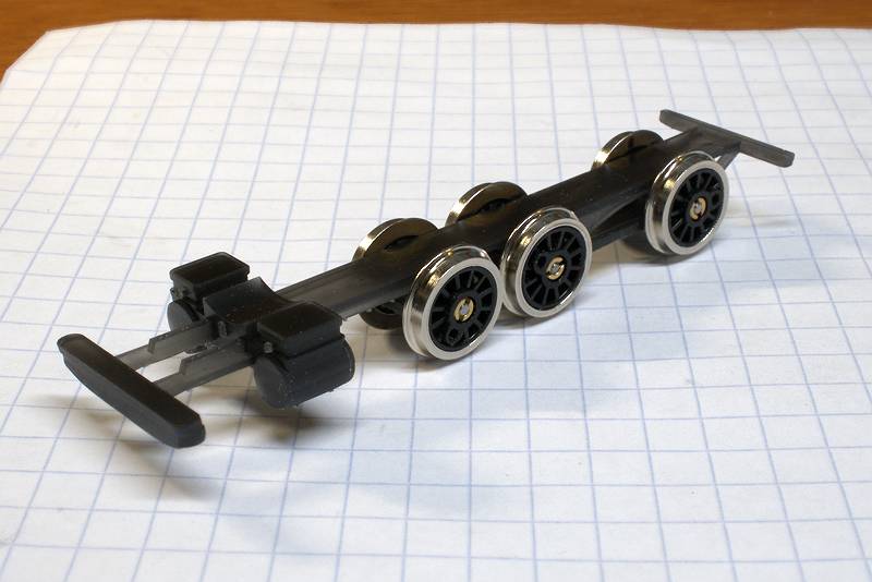
In my previous post you’ll see my original work on fabricating a frame, OSHCut laser-cut 0.02" nickel silver. Compared to the “cut-n-file” method outlined in the Odegard MR articles this was really easy and rendered perfectly-aligned driver boxes. My next step was to fabricate spacers and solder them in place to make an integral frame, but I decided to part with that tack and investigate what it would take to 3D print it. What I’m going to do with this post is try an organization model that breaks the post into two sections, “Modeling” and “Fabrication”. This is also to be Part 1 of a series, as at this date I’m not yet fully on-board with a plastic frame…
Modeling
(Top)
Note: Yes this is OpenSCAD. Thing is, I think it’s great for illustrating concepts, and sharing code that others can use. Accordingly, at the end of this section will be a code segment that most anyone can use to make a frame…
The frame was rather easy to model in 2D, and I didn’t think that’d be any different in 3D. Indeed, I think I could have found a path to import the @d .dxf file into OpenSCAD, but I decided instead to model it from scratch. My plan was to model the full frame, both sides connected with a top sill, and the shape was to be pretty much the same as the 2D model, so I just copy-pasted dimensions as I went.
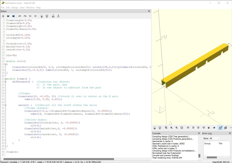
I started with a cube of the frame’s overall dimensions, then put it in a difference() operator to subtract shapes defined from a cube and cylinder to cut out the driver boxes, as well as another cube of slightly smaller dimension to carve out the frame innards. Here’s a screenshot of it:
I’ll post the final demo code at the end of the section. Of note here are a couple of conventions I’ve come to as I’ve built stuff:
-
I use the X axis as the model’s reference line. I also anchor the model to the origin (where X, Y, and Z converge) at the frame front. Now, I build parts at the origin for reasons I’ll explain in a later post, but the frame front is usually easy to determine from an erection drawing, and parts can be confidently placed referenced to that along the X axis.
-
I put all the code for a part in a module, then I call the module. As a module, the part can then be moved, scaled, or rotated en-masse. For instance, I’ll make a separate “for-print” file containing something like this:
  use <frame.scad>

  scale([25.4, 25.4, 25.4])
  	frame();
Since I’m working in inches, this scales the part to millimeters (inches x 25.4) for printing.
-
I start to think early about what components I might need to reliably move around. I then capture the relevant dimensions in variables, so I can just change the variable and all the things move correctly. In this frame example, the driver slots are set up to do that, and I can change their location simply by changing the associated *driver variable. Also set up for that is the slot width and the depth it takes out of the frame.
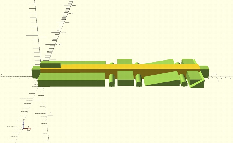
So, there’s the basic frame. Now, the prototype has some voids and other truncations that would be good to represent, so I’m going to add them to the union to be subtracted from the frame. To make the voids, I used both standard OpenSCAD cubes and, for the irregular ones, a trapezoid routine I wrote. Here’s a view of the frame with the void visiblity turned on:
and the frame with all the voids subtracted:
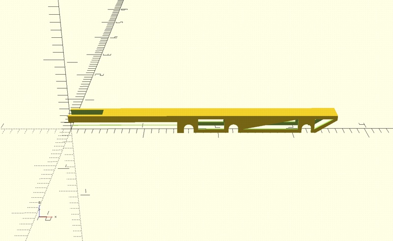
Here’s the code that produced it:
framelength=3.59;
framewidth=0.25;
frameheight=0.25;
framethickness=0.05;

slotwidth=0.129;
slotdepth=0.125;

frontdriver=1.54;
maindriver=2.14;
reardriver=3.12;

$fn=90;

module trapezoid(bottomline, topline, toplineheight, toplineoffset)
{
		pts = [
			[0,0],
			[toplineoffset, toplineheight],
			[toplineoffset+topline, toplineheight],
			[bottomline, 0]
		];
		polygon(pts);
}

module slot()
{
	translate([slotwidth/2, 0.5, slotdepth-slotwidth/2]) rotate([90,0,0])cylinder(d=slotwidth, h=1);
	translate([0,-0.5,0]) cube([slotwidth, 1, slotdepth-slotwidth/2]);
}


module frame() {
	difference() {  //contains two objects
					//	1) the part, and
					//	2) the object to subtract from the part

		//frame:
		translate([0, -0.125, 0]) //scooch it over to center on the X axis
			cube([3.59, 0.25, 0.25]);

		union() {  //subtract all the stuff within the union
			//frame channel:
			translate([-0.2,-(framewidth-framethickness)/2, -0.00001])
				cube([4, framewidth-framethickness, framewidth-framethickness/2]);

			//driver boxes:
			translate([frontdriver, 0, -0.00001])
				slot();
			translate([maindriver,0, -0.00001])
				slot();
			translate([reardriver, 0, -0.00001])
				slot();

			//inter-driver voids:
			translate([3.60, 0, 0.19]) rotate([90,180,0]) trapezoid(0, 0.3, 0.2, 0); //rear slant
			translate([3.29, 0, 0.05]) rotate([90,0,0]) trapezoid(0, 0.25, 0.15, 0); //rear void
			translate([3.07, 0, 0.20]) rotate([90,180,0]) trapezoid(0, 0.75, 0.15, 0); //main-rear void
			translate([1.73, 0, 0.05]) rotate([90,0,0]) trapezoid(0.35, 0.35, 0.15, 0); //front-main void

			//front-end carvings:
			translate([-0.00001,-0.5,0]) cube([1.45, 1, 0.16]);
			translate([-0.00001,-(framewidth-framethickness*2)/2,.2]) cube([0.45, framewidth-framethickness*2, 0.16]);
		}
	}
}

frame();
Fabrication
(Top)
I think the frame constructed above would print okay with either a filament or resin printer. But I only have one printer, resin, so with that hammer everything looks like a nail :D That choice does have ramifications, however…
One thing that starts to dominate your thinking as you design such a a thing is, how much do I add to a part? In traditional brass scratchbuilding, that determination largely came from the materials and the tooling used to shape them. The cylinder chest, for example was fabricated separately and usually soldered to the frame.
With 3D printing, one has the option to combine things, and there are good reasons to consider in making combination decisions. For instance, a part printed with the larger part to which it’s attached doesn’t require subsequent drilling and gluing. Another example, if a particular alignment is critical, it’s a lot easier to do that precisely in the CAD software than to do it during attachment. Thinking through that, I decided to incorporate the cylinder chest, which I’d already designed, and the front and back bolsters. This is why I define my parts as modules; to add the cylinder chest, it was as simple as doing this:
use <../CylinderChest/cylinderchest.scad>

...

DRG_168_frame();
translate([0.45,0,0.143]) cylinderchest();
to get this:
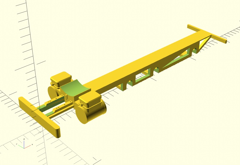
Note that I did some additional frame shaping up front, as well as detailing and adding the bolsters pretty much in the same way. Oh, and if you look closely, you’ll see frame crossmembers at various places around the driver slots, this is for supporting brass clip-on plates I’m considering for closing the slots containing the axles (for another post…)
Now, there are some parts of the frame that are rather beefier than their prototype counterparts. I think this is a factor long-established in scale modeling: laws of physics keep us from precisely copying every dimension of a prototype in some small scale like HO. Resin and filament printing have their own constraints regarding this; for instance, I was wondering how those snifter valves on the cylinder chest fronts would survive resin printing, washing, and curing. The beauty of this process is, if something like this doesn’t work, printing it again with a change is relatively cheap. As of today, I’m on my fourth frame print, and I’ve got changes queued for the fifth.
So, I did all the above thinking with respect to my medium, resin. Some of the decisions would be different if I were using a FDM printer.
On to printing. First, this model was created in actual inches, HO scale. The default measurment scale in 3D printing is millimeters, so the model has to be scaled to those dimensions. What I’ve come to do in assembling parts for #168 is to model them in inches, then make a separate .scad file with “forprint” appended to the name, e.g., ‘168_frame-forprint.scad’. The contents of that file look just like the code snippet I described above where the part is scaled by 25.4 in all three axes. That does the inch-millimeter conversion, and is the version that I render for printing.
The renders we’ve been looking at are not printable; instead, a separate render is required to produce the mesh that’s saved to a .stl file, recognized by the slicer software. I just did that on my tablet here, and that render took 2 minutes, 11 seconds. OpenSCAD developers are working on significantly reducing that, thank goodness, the smokebox-boiler-firebox is much worse…
Now, I’m new to this so I’ll take any feedback on my choice of supports. I oriented the model horizontally, based on my bit of experience printing a few small parts; I wanted the layer texture to run horizontal in the cylinders and chests. I did the first print with the auto-generated supports, and I got drooping bolsters and a few wobbly places on the frame bottom edge:
Armed with that information, for the next print I manually placed the supports, all around each edge that presented itself to the build plate and I double-alternating supported the large bolster. Here’s a screenshot of the frame in the slicer:
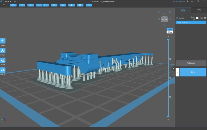
This time I got good definition in most of the model, still with a bit of waviness in the main-rear void, the slanted one that’ll be under the firebox.
Regarding details, this medium never ceases to amaze me. Here’a a closeup of one of the snifter valves:
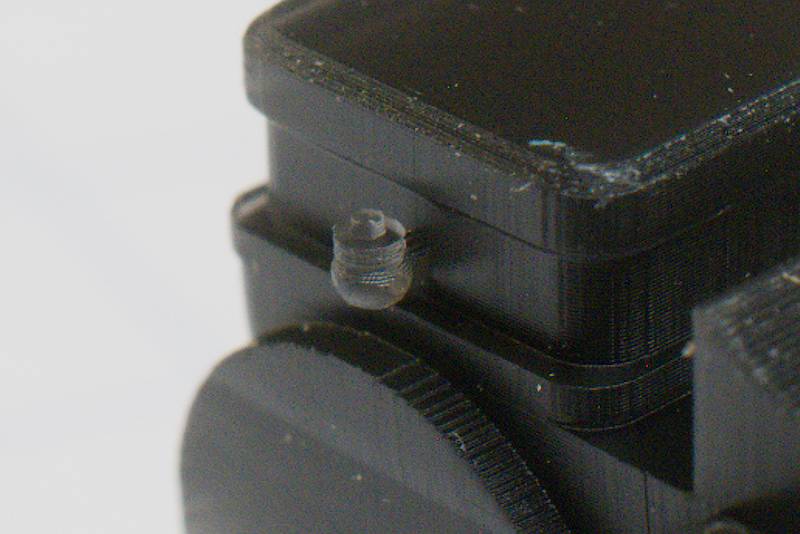
There are also bolt heads on the nearby frame members, representing the frame extension made to #168 to accommodate a snowplow, according to folk at the Cumbres & Toltec.
So, I had various other issues in the first four prints, frame too wide, tight driver slots, slots too high putting the drivers against the boiler. I’ve dialed in adjustments for all, which are included in the model demo constructed for this post. What I haven’t yet figured out is that the front part of the frame will cure with a bit of a droop. I added to the vertical frame dimension (lowered the cutout) in the space between the front drivers and the cylinder chest, but I haven’t printed that yet awaiting delivery of an order of “ABS-Like” resin. This design will essentially use the frame itself as driver bearings, so I want to mess with a few different “harder” resins to see how they’ll interact with the spinning axles. The finish-up of the frame with respect to that experimentation, as well as a bit of discussion/demonstration of an alternate nickel-cut frame design (both halves joined at the top by spacers included in the part, frame sides bent down to form the part) will be the topic of Part II.
Frankly, so far I’m very pleased with the frame design and print rendition. I’ll happily take discussion at any of the forums I frequent: Trainboard, MHR, and the Google HOn3 mailing list.