DRG #168's Smokebox, Boiler, and Firebox
Roll your own!
Table of Contents:
The smokebox-boiler-firebox of a steam locomotive is the largest and most visible assembly of most steam locomotives, so IMHO it’s imperative that it looks nice. That thinking goes to textures and finishes as well as detailing. Modeling them can be dirt-simple, or quite complex, depending on the structure’s overall shape. Indeed, I’ve seen writings on scratchbuilding particular locomotives where a length of fortuitously-diametered brass pipe was used for the entire structure. While #168 overall is fairly simple to model, its tapered boiler presents a bit of a challenge past the “straight pipe” approach. And, it’s not a symmetric cone; the taper is greatest at the top, and it gradually decreases to where the bottom aligns level with the rest of the boiler.
When I planned to roll this structure in brass, I found software and an article describing the process that made laying out the flat to be rolled into the taper fairly simple (a bit more on it here. I followed that process and got OSHCut to laser-cut a flat that would roll right into the properly-shaped tapered course. That’s as far as I got before I switched gears to 3D printing. I may yet roll the flats into courses and solder them together to see how it would have gone…
Fabricating such a boiler course in CAD is not as tough, but does require a bit of “geometry” to orient it correctly. I’ll try to do that justice below.
Modeling
(Top)
Modeling a boiler in OpenSCAD requires a shape that’s not native to the program, a hollow cylinder. Third-party OpenSCAD libraries such as BOSL have such shapes, but I’m going to do it “by hand” to demonstrate the use of subtraction and the OpenSCAD difference() operator to build complex shapes. Here are the two modules I wrote to facilitate boiler construction:
module boilercourse(diameter, length, thickness)
{
	rotate([0,90,0])
	difference() {
		cylinder(d=diameter, h=length);
		translate([0,0,-thickness*0.01]) cylinder(d=diameter-thickness, h=length+thickness*0.02);
	}
}

module taperedcourse(diameter1, diameter2, length, thickness)
{
	rotate([0,90,0])
	difference() {
		cylinder(d1=diameter1, d2=diameter2, h=length);
		translate([0,0,-length*0.01]) cylinder(d1=diameter1-thickness, d2=diameter2-thickness, h=length+length*0.02);
	}
}
Essentially, each module defines a regular OpenSCAD cylinder, then subtracts a slightly smaller cylinder from it using the difference() operator. Note that the subtracted cylinder is smaller in diameter than the first one by the value of thickness, and it’s translated up by the value of thickness, and “back” by half the value of thickness to compensate for the exact same position of both parts. The length of the subtracted shape only has to be just a bit longer than the length of the part from which it’s subtracted, so there’s not a “thin film” of material left at the ends.
Take note of the rotate([0,90,0]); cylinders in OpenSCAD by default are erected “vertically”, at the origin along the Z axis. I want to deliver parts to other files oriented along the X axis, and that rotation on the Y axis turns the boiler course to be centered on the X axis with its front at the origin. That’s important to placing parts in correspondence with the erection drawing, they can be translated using a measurement in the X axis that directly corresponds to its distance from the frame front at X=0.
What I started doing with modules like these is to collect them into a “utilities.scad” file. Some become useful in other parts and this makes it easy to get to them. One of the re-uses occurred almost immediately; I used boilercourse() to model the boiler straps.
From front to rear, let’s lay out the courses:
Smokebox
(Top)
Shape-wise the smokebox is simple, a single boilercourse:
boilercourse(diameter=0.61, length=0.6, thickness=0.05);
I came to the value of 0.05" for the thickness after the first print at 0.02", which was flexible like a soda straw…;
The harder part of the smokebox comes with the decorations. First, the prototype has rivet patterns both horizontal and radial around the diameter. After a bit of thinking, I designed a few modules to lay out rivets in various courses:
rivet_height = 0.01;
rivet_diameter = 0.02;
rivet_top=0.005;

module rivet_cylinder(diameter=0.2, start_deg=0, end_deg=90, spacing_deg=10)
{
	for(angle = [start_deg: spacing_deg : end_deg])
		rotate([angle, 0, 0])
			translate([0,0,diameter])
				cylinder(d1=rivet_diameter, d2=rivet_top, h=rivet_height);
}

module rivet_circle(diameter=0.2, start_deg=0, end_deg=90, spacing_deg=10)
{
	for(angle = [start_deg: spacing_deg : end_deg])
		rotate([angle, 0, 0])
			translate([0,0,diameter])
				rotate([0,-90,0]) cylinder(d1=rivet_diameter, d2=rivet_top, h=rivet_height);
}

module rivet_course(start_x= 0, end_x=1, spacing=0.1)
{
	for(pos = [start_x: spacing : end_x])
			translate([pos, 0, 0])
				cylinder(d1=rivet_diameter, d2=rivet_top, h=rivet_height);
}
Note that all three modules make a rivet as a conical cylinder with the dimensions defined in the variables at the top of the code segment.
All three of these modules use the for-loop of the OpenSCAD language to place a sequence of rivets. rivet_course() lays a straight line, using the loop counter to increment the X value of translate() call that moves the rivet. Here’s what you get just using the defaults:
rivet_course();
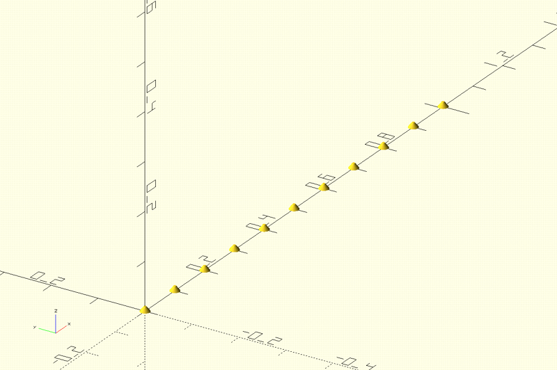
To locate the rivets on the boiler takes advantage of the specific sequencing of doing a translate(), followed by a rotate() to place them. Using this sequence takes advantage of the behavior of the movement operators to work “at the origin”, that is, the values you specify for rotate() and translate() work from the origin. So, if we translate() the rivet course up on the Z axis to the boiler diameter, then rotate() it on the X axis the appropriate number of degrees, the rivets will be placed in the right position on the boiler course oriented in the proper direction. So this code:
boilercourse(0.61, 0.6, 0.05);
rotate([120,0,0])
	translate([0,0,0.61/2])
		rivet_course(start_x= 0.04, end_x=0.54, spacing=0.05);
lays out the smokebox and places and orients the first rivet course where it’s supposed to go:
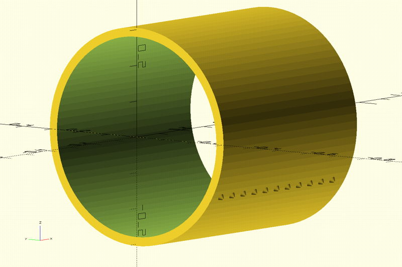
Note the indentation of the code, that helps us see the relationship of the operators. The innermost one is done first, laying out the rivets on the X axis. The next one up, translate(), moves the course to the outer edge of the course on the Z (up) axis, then the outermost one, rotate(), rotates the course around the boiler diameter to the right place.
rivet_cylinder() and rivet_circle() use the same translate-rotate sequence to position rivets. So, this code:
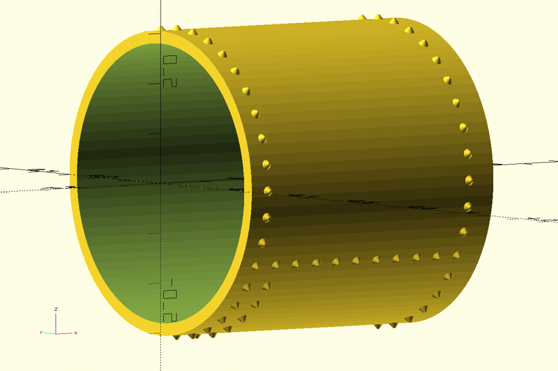
boilercourse(0.61, 0.6, 0.05);

rotate([120,0,0])
	translate([0.04,0,0.61/2])
		rivet_course(start_x= 0, end_x=0.54, spacing=0.05);
rotate([-120,0,0])
	translate([0.04,0,0.61/2])
		rivet_course(start_x= 0, end_x=0.54, spacing=0.05);
translate([0.04,0,0])
	rivet_cylinder(diameter=0.305, start_deg=0, end_deg=360, spacing_deg=10);
translate([0.09, 0, 0])
	rivet_cylinder(diameter=0.305, start_deg=120, end_deg=240, spacing_deg=10);
translate([0.54, 0, 0])
	rivet_cylinder(diameter=0.305, start_deg=0, end_deg=360, spacing_deg=10);
makes this:
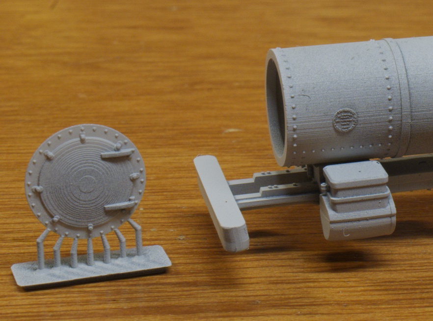
There are other decorations that’ll adorn the final smokebox: the smokebox front, builder’s plaque, handrails and stanchions, number plate. I’ll save those for subsequent posts as they deserve singular attention.
Boiler
(Top)
Yeah, the boiler actually extends all the way back into the cab, but I’m separating the two courses before the firebox so we can discuss the tapered course…;
So, this part of #168’s boiler has two courses, a regular course of diameter=0.61" and length=0.4", then a tapered course with a forward diameter=0.61", length=0.5", and a rear diameter=0.65". The tricky part is the cant of the tapered course so the bottom is level. Actually, not so tricky:
rotate([0,-2.3,0]) //tapered cant, bottom rests on x-axis
	translate([0,0,0.61/2]) //bottom-front on x-axis
		taperedcourse(0.61, 0.65, 0.5, 0.05);
The tapered course is laid out per the dimensions given, which gives a symmetric cone. By default, it is centered around the X axis, so the translate() moves it up so the bottom-front edge sits right on the origin. This position is important because it is going to tell us how much to rotate the course so the bottom-rear edge also sits on the X axis, This is what it looks like at the aft end after the translate():
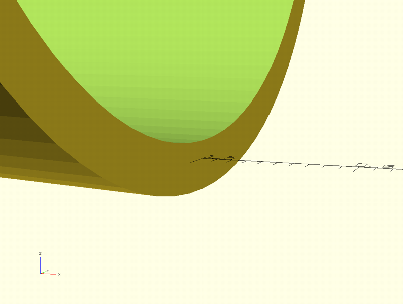
Note that the axis line runs through the boiler material; what we want to do is to rotate() the boiler course up so that line is on the bottom of the course like it is on the front. In the code above, that -2.3 is the number of degrees it takes, and the result looks like this:
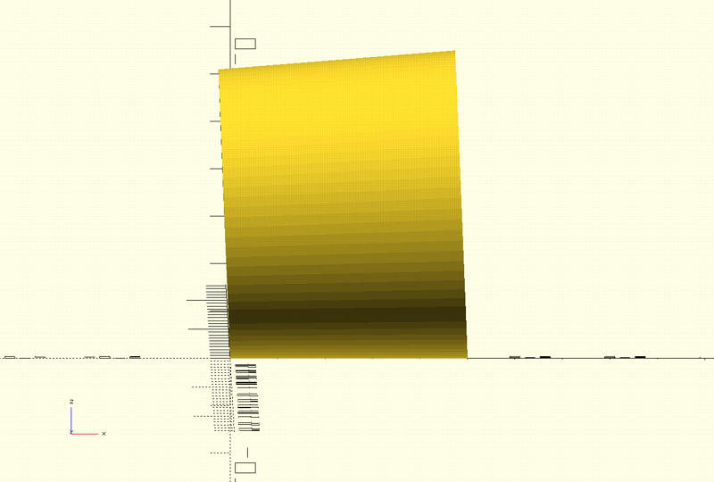
How did I determine -2.3? Well, I started with -2, rendered that and looked at where the axis line was, then iterated through increasing degrees incremented by -0.1 until I got to -2.3. I do that sort of thing a lot, positioning things incrementally until they’re in the right place. Yeah, a mouse-move thing in FreeCAD would be easier, but I actually like the control I get doing it this way.
Now, one could do a difference() of the course with a couple of cubes to make the front and back parallel to the vertical, but I take care of that by joining the adjacent courses so the excess material gets embedded in the adjacent course. Probably not kosher mesh-wise, but I get a printable part. Here are the two courses joined, with straps made from really small and thin boiler courses, first the code:
module boiler() {
	//first course:
	translate([0,0,0.61/2]) {
		boilercourse(0.625, 0.04, 0.04);  //strap
		translate([0,0,0]) boilercourse(0.61, 0.4, 0.05);   // first course
		translate([0.37,0,0]) boilercourse(0.625, 0.04, 0.04);  //strap
	}

	//second (tapered) course:
	translate([0.41,0,0]) //move down centerline to its position
		rotate([0,-2.3,0]) //tapered cant, bottom rests on x-axis
			translate([0,0,0.61/2]) //bottom-front on x-axis
					taperedcourse(0.61, 0.65, 0.5, 0.05);  //second course
}

boiler($fn=90);
then the render:
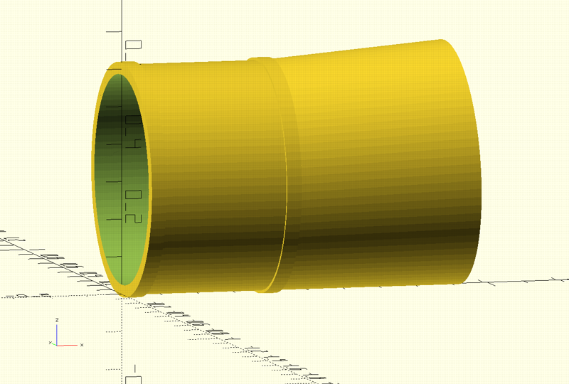
By the way, the $fn=90 in the call to the boiler module is telling the code in the module to calculate circles with 90 faces. The default is 6, which doesn’t look to good, although works really well in making bolt heads. I’ll have more to say about $fn in Fabrication…;
Firebox
(Top)
The firebox is a single course, but the bottom is amended with the straight sides that go into the frame at a slant. The straight sides also have rivets, but we know how to do that. We start with a straight course of the required dimensions, then use a cube to subtract out the bottom. Add the sides and decorate with rivets. Here’s the complete code:
thick=0.02;
gap=0.25;

module firebox_sides() {

	//firebox pan sides:
	difference() {
		union() {
			translate([0,-(gap/2+thick),0])
				cube([0.96,thick,0.3]); //port side
			translate([0,(gap/2),0])
				cube([0.96,thick,0.3]);  //starboard side
		}
		translate([0,0,-0.19])
			union() {
				translate([.50038,-.3,.11778]) cube([.5,.6,.2]);  //horizontal bottom edge
				translate([0,-.3,0]) rotate([0,-12.7,0]) cube([.558,.6,.2]); //slanted bottom edge
		}
	}

	//firebox pan front:
	translate([0,-(gap/2+thick),0.2]) roundedbox([0.05,gap+thick*2,.1], 0.005);

	//firerbox rivets:
	//port side:
	translate([0.02,-(gap/2+thick),0.27])
		rotate([90,0,0]) rivet_course(start_x= 0, end_x=0.94, spacing=0.05);
	translate([0.02,-(gap/2+thick),0.27-0.04])
		rotate([90,0,0]) rivet_course(start_x= 0, end_x=0.94, spacing=0.05);
	translate([0.02,-(gap/2+thick),0.27-0.08])
		rotate([90,0,0]) rivet_course(start_x= 0, end_x=0.94, spacing=0.05);
	translate([0.02,-(gap/2+thick),0.27-0.12])
		rotate([90,0,0]) rivet_course(start_x= 0, end_x=0.94, spacing=0.05);
	translate([0.02,-(gap/2+thick),0.27-0.16])
		rotate([90,0,0]) rivet_course(start_x= 0, end_x=0.3, spacing=0.05);
	translate([0.02,-(gap/2+thick),0.27-0.20])
		rotate([90,0,0]) rivet_course(start_x= 0, end_x=0.1, spacing=0.05);

	//starboard side:
	translate([0.02,gap/2+thick,0.27])
		rotate([-90,0,0]) rivet_course(start_x= 0, end_x=0.94, spacing=0.05);
	translate([0.02,gap/2+thick,0.27-0.04])
		rotate([-90,0,0]) rivet_course(start_x= 0, end_x=0.94, spacing=0.05);
	translate([0.02,gap/2+thick,0.27-0.08])
		rotate([-90,0,0]) rivet_course(start_x= 0, end_x=0.94, spacing=0.05);
	translate([0.02,gap/2+thick,0.27-0.12])
		rotate([-90,0,0]) rivet_course(start_x= 0, end_x=0.94, spacing=0.05);
	translate([0.02,gap/2+thick,0.27-0.16])
		rotate([-90,0,0]) rivet_course(start_x= 0, end_x=0.3, spacing=0.05);
	translate([0.02,gap/2+thick,0.27-0.20])
		rotate([-90,0,0]) rivet_course(start_x= 0, end_x=0.1, spacing=0.05);
}

module firebox_course() {
	translate([0,0,0.65/2]) {   //bottom on x axis
		difference() {
			union() {
				boilercourse(0.65, 1.4, 0.05);  //third course
				boilercourse(0.66, 0.04, 0.04);  //strap
				translate([0.52,0,0])
					boilercourse(0.66, 0.04, 0.04);  //strap
			}
			translate([.5,-(gap/2),-0.45])
				cube([1,gap,0.27]); //smokebox bottom cutout
		}
	}
}

module firebox() {
	firebox_course();
	translate([0.47,0,-0.25])
		firebox_sides();


}

firebox($fn=90);
I chose to factor the part into two sub-modules, firebox_sides() and firebox_course():
- firebox_sides() makes the two sides as two cubes, and subtracted from them both is a set of cubes to make the bottom edges. Next, there’s a rounded_box() placed to make the front of the lower firebox. The rest of the code lays out rivet_courses on both sides. Note: rounded_box() is not native to OpenSCAD, another module I wrote for utilities.scad.
- firebox_course() is essentially the boilercourses that make the course and two straps, and subtracted from that is a cube that makes the opening at the bottom.
The two sub-modules are combined in the firebox() module, with the firebox sides translated into place at the edges of the course’s bottom cutout.
Of note are the two variables declared at the top, thick and gap. These variables identify what I’d determined to be the things that I might need to change as I did various integration things, like fitting the assembly to the frame. Whereever that dimension played a role in some equation I used the variable. So, whenever I change the variable value, all the affected dimensions changed to suit. In subsequent integration exercises, I’ve used gap in particular, as I iterated through a couple of prints getting the frame width good to clear the drivers. I’m not addressing motorization right now; that’ll probably be another opportunity to tweak these two variables.
The Smokebox-Boiler-Firebox Assembly
(Top)
In previous posts I talked about the decisions to be made in how many sub-assemblies should be integrated for printing a single part. I initially intended to print the parts described above separately, as they had their own considerations for their surface texture. Specifically, the boiler courses are quite smooth; on the prototype the exposed surface is stainless-steel cladding. The smokebox surface, however, is the raw steel of the structure. However, I decided to integrate the parts for printing to try various printing orientations to optimize the surface texture. So, I created a smokebox-boiler-firebox.scad file that looks like this:
use <smokebox.scad>
use <boiler.scad>
use <firebox.scad>

$fn=90;

module smokebox_boiler_firebox() {
	smokebox();
	translate([0.6,0,0]) boiler();
	translate([1.48,0,0]) firebox();
}

smokebox_boiler_firebox();
Quite simple, the use statements make the individual parts available, and the smokebox_boiler_firebox() module renders the parts translated into position. Of note is the $fn=90; statement; that value turned out to be a concern in printing, which I’ll talk about later. The bottom line calls the module to render it for viewing, so here’s the result:
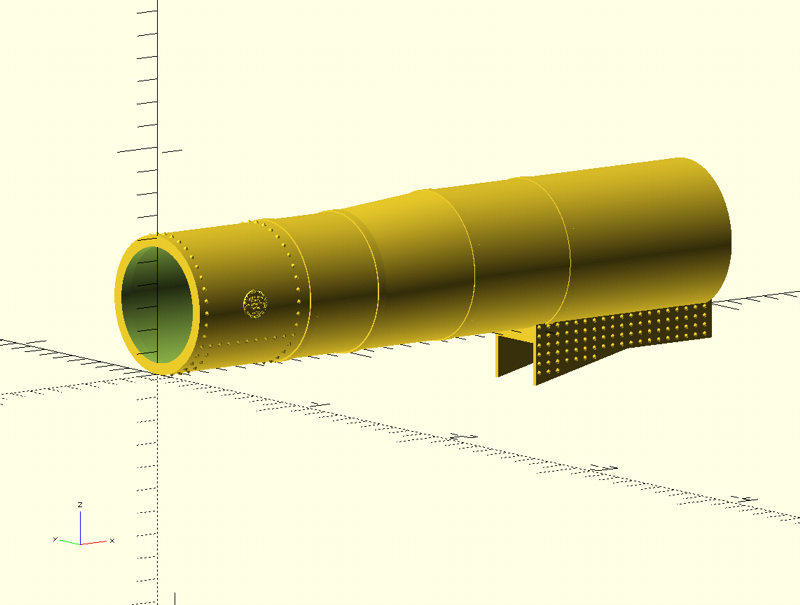
There are a couple of addtions of note, left-to-right:
- On the front edge of the smokebox, I added an inner boilercourse() to make a mounting surface for the smokebox front.
- I put the builder’s plate on both sides of the smokebox.
Fabrication
(Top)
I started by making my usual _forprint.scad file:
use <smokebox_boiler_firebox.scad>

scale(25.4)
	smokebox_boiler_firebox($fn=360);
So, after a bit of trial and error I’ve decided to defer two things to the _for_print.scad file: 1) print scale, and 2) number of faces for circular stuff. Scale, I that got early on; I needed to design in inches, and printers and printing software wanted millimeters, so applying the scale(25.4) is the primary purpose of the file. The $fn setting for the number of faces in a circle is recent; I’ve been randomly setting it as a global variable in various places, but I discovered those could end up in the print, to lesss-than-desirable outcomes. OpenSCAD modules let you set that variable when you call a module, like I have in the _forprint code above, and that lets one isolate its use to specific invocations.
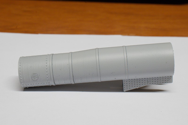
To support the model for print, I went with Jeff Kraker’s approach, straight-up vertical. I chose to support it at the backhead end, because I wanted a smooth surface on the front to which to glue the smokebox front. Added supports for the slanted part of the firebox pan sides, and that was it.
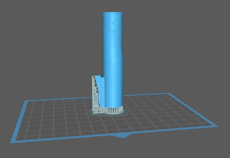
In the first part I printed, the oh-so-tiny compressor, $fn=90 worked fine because the face sizes on that small-diameter part were closer to the printer layer resolution. However, in the larger parts, that same number showed up prominenty:
As far as I can see, the slicer and printer are trying to faithfull render the geometry it was presented. So, for the most recent print, I rendered the mesh for the .stl file at $fn=360:
Here’s the OpenSCAD view renders for both settings:
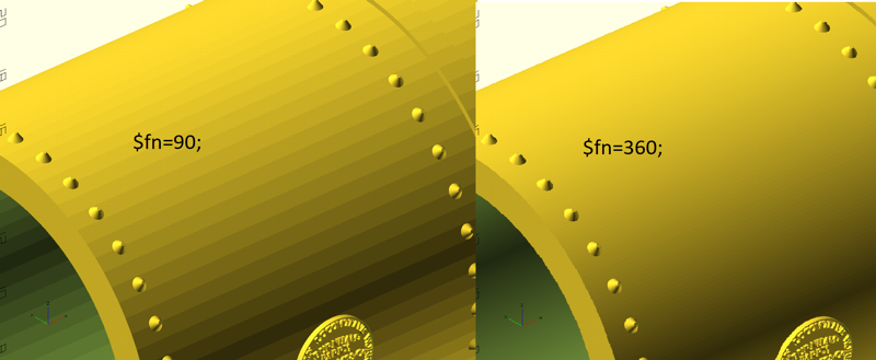
The problem with $fn=360 is that the mesh render for the .stl file took 1 1/2 hours. Now, that really isn’t a problem per se; I can kick off something like that, go do something else and come back when done. It does get in the way of iterating parts for fit checks and such, but I think those parts can be rendered with less such resolution. I’m collecting a few such things to reserve for “final print”, $fn, layerheight and corresponding exposure time are what I have so far.
Of note in the most recent print are the periodic concentric rings, starting in the tapered course and occurring going-left all the way into the smokebox. I have a theory, I left the thermostat-controlled heater running during the print and I believe when it would start, its inrush current robbed current from the printer, possibly affecting the brightness of the UV LED array. One of those, “Hurts when I do that! Well, don’t do that…;” things.
All-in-all, I’m pretty happy with this part. It’s still not finished, needs various decorations (stanchions, footboard supports, maybe generator and compressor brackets), as well as frame attachment mechana (nuts for screws, tabs, haven’t decided how yet).