DRG #168's Cab
Extruding fun!
Table of Contents:
Making #168’s cab was pretty straightforward, except for the roof. The gradual curve wasn’t too hard to model, but the tail extending past the cab’s end required use of an extruded profile. And, the cab box and floor have detail on all four sides, which proved to be a schooling in supports for printing. This post will also include a couple of additional resources, software to aid in doing the extrusion and a library of modules to make complex curved surfaces and edges.
Modeling
(Top)
The cab is an exercise in the CAD-equivalent of whittling, ‘removing material until it looks like a horse.’ :D OpenSCAD difference() operators are used to shape the front and both sides, carving out windows and insets. I wrote the code as an overall cab() module with two sub-modules, cab_roof() and cab_side(). The cab_side() module was used twice to make each side, one of them called with the OpenSCAD mirror() operator to reverse it for the other side. The cab_roof() was separate because I spent time developing alternatives in a separate file, so I just surrounded the best one with the code to make it a module. Here’s the cab_roof() code:
module pie_slice(ang=30, l=1, r=1, spin=0)
{
echo(ang, l, r, spin);
rotate([0,0,spin])
difference() {
cylinder(r=r, h=l);
translate([-r, -r, -l/2])
cube([r*2,r,l*2]);
rotate([0,0,ang])
translate([-r, 0, -l/2])
cube([r*2,r,l*2]);
}
}
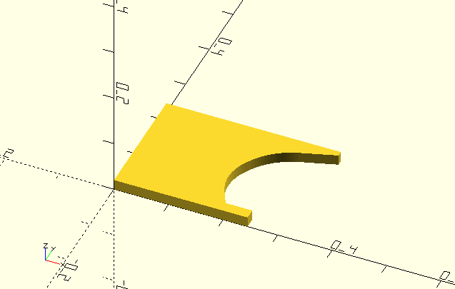
module cab_roof(arc=90, radius=30, length=20, thickness=1)
{
translate([length,0,-radius-thickness]) rotate([0,-90,0]) {
//roof:
difference() {
pie_slice(ang=arc, l=length, r=radius+thickness, spin=-arc/2);
translate([0,0,-length/2]) pie_slice(ang=arc*2, l=length*2, r=radius, spin=-(arc*2)/2);
}
//roof edges:
rotate([0,0,-arc/2]) translate([radius+thickness/2,0,0]) cylinder(d=thickness, h=length);
rotate([0,0,arc/2]) translate([radius+thickness/2,0,0]) cylinder(d=thickness, h=length);
}
}
The pie_slice() module makes a shape like you would think, two sides arranged on an angle with a curved side at the opposite end. The BOSL/BOSL2 libraries have such a module, but I decided to code it for myself when I ran into a problem I’ll describe later in the post. The cab_roof() module essentially makes the roof as the difference of two pie_slice() calls, one slightly smaller than the other. I determined the roof radius with a paper copy of the #169 drawing and a protractor. I finished the roof by adding a couple of thin cylinders to make rounded edges.
I started to model the cab sides by making a cube and carving out the tail with cubes and cylinders, but I quickly scrapped that in favor of defining a polygon (an array of points) that looked like the cab side profile, then using OpenSCAD’s linear_extrude() to make a 3d shape using the polygon. Here’s the code to do that:
include <Round-Anything/polyround.scad>

side_pts = [
[0.0000,0.0000,0.0000],
[0.0000,0.7200,0.0000],
[1.1500,0.7200,0.0000],
[1.1500,0.7000,0.0000],
[0.7940,0.6580,0.07000],
[0.7800,0.6300,0.0000],
[0.7500,0.6300,0.0000],
[0.7500,0.6300,0.0000],
[0.7500,0.0000,0.0000]
];

module cab_side() {
	difference() {
		linear_extrude(0.04) polygon(polyRound(side_pts), 30); //side overall shape
		union() {
			translate([-0.0001,-0.001,0.03])
				cube([1,0.63,0.39]); // crown offset
			translate([0.06, 0.07, 0.02])
				cube([0.6, 0.1, 1]);  //number board inset
			translate([0.06,0.24,0.02])
				cube([0.28,0.38, 1]);  //forward window inset

			panewidth=0.11;
			paneheight=0.16;
			translate([0.08,0.26,-0.01])
				cube([panewidth, paneheight, 1]);  //forward window pane
			translate([0.21,0.26,-0.01])
				cube([panewidth, paneheight, 1]);  //forward window pane
			translate([0.08,0.44,-0.01])
				cube([panewidth, paneheight, 1]);  //forward window pane
			translate([0.21,0.44,-0.01])
				cube([panewidth, paneheight, 1]);  //forward window pane

			translate([0.39,0.24,-0.5])
				cube([0.28,0.38, 1]);  //rearward window
		}
	}

	translate([0.38,0.24,0]) cube([0.3,0.02,0.05]); //window sill

}
The array of points, side_pts, describes the outline of the cab side. Can you see it? I can’t…
After manually scooching around x and y values to make a bell outline, I decided this was one thing where I needed an interactive tool. So, I cobbled together a program, wxpolygon, that does this. Here’s a screenshot of wxpolygon with the side_pts array loaded:
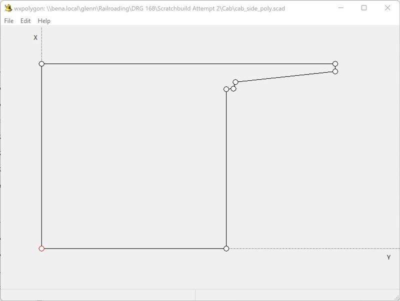
Looks more like a cab side, no? The points can be added and moved with the mouse. Right-clicking on a point opens a dialog with the x, y, and r values (more on r in a bit) for editing. Once you have the polygon shape you want, you can copy/paste the point array right into an OpenSCAD script or save it in a .scad file that you can use<> from another script. The link to wxpolygon is in the Resources at the end of the post.
If you look at #168’s cab in the drawing, the roof tail has a curve in the tail support. In order to insert that into the polygon, I use an OpenSCAD library called, aptly, Round-Anything. Among some other useful things, its polyRound() module will take a polygon with points defined as three numbers, x, y, and r for ‘radius’, and insert the points to make a curve of the specified radius at that point. Take a look at side_pts, each point has three values, and the fifth point has a non-zero third value, 0.07. In the code, here’s the line that does the magic:
linear_extrude(0.04) polygon(polyRound(side_pts), 30); //side overall shape
Working the way from innermost to outermost, polyRound() is called with side_pts, and its call is in turn in the call to OpenSCAD’s polygon() module. The result of all that is used by linear_extrude to make the 3D shape, with a thickness of 0.04. One thing of note is that Round-Anything’s polyRound() expects a point array with three values for each point, x, y, and radius. OpenSCAD’s polygon() expects just two values for each point, x and y. If you inadvertently call one or the other with the wrong array, expect to wait a bit for all the error messages to finish. A link to Round-Anything is in the Resources section.
linear_extrude() just pulls a 3D shape out of the 2D polygon of the desired thickness. Extrusion is a core concept of CAD modeling; if your CAD program doesn’t have some form of extrusion tool, making complex shapes will be a lot harder…
The rest of the cab_side() module is just a difference() between the profile extrusion and a bunch of shapes collected in the OpenSCAD union() operator. These shapes cut the windows and make the indentations. After that grand difference(), there’s a cube added for the window sill.
The cab sides were incorporated in the cab() module like this:
translate([0, -0.49, 0]) rotate([90,0,0]) cab_side();
translate([0, 0.5, 0]) rotate([90,0, 180]) mirror([1,0,0]) cab_side();
The second cab side is first mirrored in the X axis while the part is “laying flat”, so everything drawn is rendered backwards for the other side. Both parts have to be rotated in the X axis to stand them up, and the translate moves each to the respective side along the Y axis.
The cab front and back are the same thing as the sides, except I just did them in-line in the cab() module.
Here’s the whole module:
module cab() {

	//front wall:
	difference() {
		union() {
			rotate([0,0,90]) translate([-0.50,0,0]) rotate([ 90,0,0]) linear_extrude(.03) polygon(polyRound(front_pts1));

		}
		union () {
			//front doors:
			//translate([-0.25,-0.47,0.08]) cube([1,0.12,0.53]);
			//translate([-0.25,0.37,0.08]) cube([1,0.12,0.53]);

			difference() { //left front door outline
				translate([-0.0001,-0.47,0.08]) cube([0.02,0.12,0.53]);
				translate([-0.0001,-0.46,0.09]) cube([0.02,0.10,0.51]);
			}
			difference() { //right front door outline:
				translate([-0.0001,0.37,0.08])  cube([0.02,0.12,0.53]);
				translate([-0.0001,0.38,0.09])  cube([0.02,0.10,0.51]);
			}

			//front door windows:
			translate([-0.0001,-0.445,0.38]) cube([0.1,0.07,0.2]);
			translate([-0.0001,0.395,0.38]) cube([0.1,0.07,0.2]);

			//front door insets:
			translate([-0.0001,-0.445,0.13]) cube([0.01,0.07,0.2]);
			translate([-0.0001,0.395,0.13]) cube([0.01,0.07,0.2]);

			//front windows:
			translate([-0.25,-0.27,0.51]) cube([1,0.14,0.1]);
			translate([-0.25,0.15,0.51]) cube([1,0.14,0.1]);

			//firebox opening:
			translate([-0.001,0,0.18]) rotate([0,90,0]) cylinder(d=0.66, h=1);
			cube([1, 0.66, 0.4], center=true);
		}
	}

	translate([-0.0001,0.395,0.13]) cube([0.01,0.07,0.2]);

	//rear wall:
	difference() {
		translate([0.72,-0.5,0]) rotate([ 90,0,90]) linear_extrude(.03) polygon(polyRound(rear_pts));
		union() {
			translate([0,-0.45,0.44]) cube([1,0.14,0.23]);
			translate([0,0.33,0.44]) cube([1,0.14,0.23]);

			translate([0.74,-0.45,0.1]) cube([1,0.14,0.25]);
			translate([0.74,0.33,0.1]) cube([1,0.14,0.25]);
		}
	}
	translate([0, -0.49, 0]) rotate([90,0,0]) cab_side();
	translate([0, 0.5, 0]) rotate([90,0, 180]) mirror([1,0,0]) cab_side();

	translate([-0.02,0,0.81]) cab_roof(arc=36, radius=1.75517, length=1.2, thickness=0.02);

}
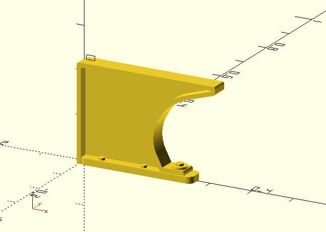
The cab floor is a separate module, as I first intended to print it and the cab separately. For reasons I’ll describe in the Fabrication section, I decided change that and print them as one part; I integrated them in the _forprint.scad file.
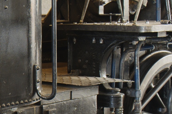
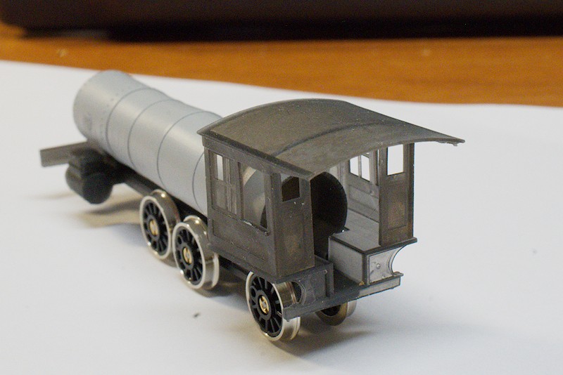
The cab floor is an interesting component; the floor itself is a simple flat piece and cut to fit the firebox and backhead, with a channel running down the middle. I modeled it with a cube difference()-ed with other cubes to do the cutouts, and the frame_channel() module from the utilities.scad file. However, the floor is supported in the rear by a casting, a somewhat ornate flange-and-fill part. This design is common to at least a few Baldwin locomotives for which I’ve seen photographs; here’s a picture of it, a crop of a photo I took of #168 at Antonito while it was being restored to operation:
To model this part, I started with a polygon of the web center, laid out with wxpolygon:
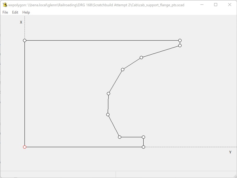
and here are the points for the polygon:
cab_support_flange_pts = [
[0.0000,0.0000,0.0000],
[0.0000,0.2200,0.0000],
[0.3200,0.2200,0.0000],
[0.3200,0.2100,0.0000],
[0.2410,0.1850,0.2000],
[0.2020,0.1600,0.2000],
[0.1730,0.1100,0.2000],
[0.1720,0.0670,0.2000],
[0.1960,0.0200,0.0000],
[0.2450,0.0200,0.0000],
[0.2450,0.0000,0.0000]
];
Note the 0.2 radi in points 5-8, that forms that smooth curve of the outer edge.
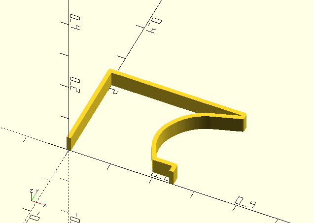
I needed to do two things with that point array: 1) make the outer-edge flange, and 2) make the fill inside the flange. Round-Anything has a neat module for making abritrarily-shaped things, beamChain(). Given a list of three-valued points like cab_support_flange_pts, beamChain() will shape a beam that follows the points, with the appropriate radii. So, this code:
linear_extrude(.04)
	polygon(
		polyRound(beamChain(cab_support_flange_pts, offset1=-0.005, offset2=0.005),30)
	);
makes this shape:
This code uses the same point array to make the fill:
translate([0,0,fillposition])
	linear_extrude(.02)polygon(polyRound(cab_support_flange_pts,30));
which looks like this:
Add some cubes and cylinders to make the rest of the part and this is the result:
Fabrication
(Top)
So, I set out to make my _forprint.scad file and ran into a problem. The nicely shaped cab roof in the design .scad file turned into a poorly-shaped mess in the _forprint.scad file. I originally used the BOSL pie_slice() routine to shape the cab, thought there might be a problem with two levels of export of its code, and that’s why I coded my own pie_slice(). Turns out it presents the same problem, so there’s a more fundamental thing going on. I’ll eventually figure it out, but my first order of business is to model a locomotive, so I just did the _forprint stuff in the cab.scad file:
scale(25.4)
	cab();
I messed around a bit with how to handle the cab floor. First, I thought it would go well integrated with the frame, but I couldn’t come up with a printing orientation that wouldn’t compromise either the floor or the cylinders already on the frame. Okay, there’s a common surface between the frame and floor that’ll make it easy to glue, so I just printed it separately with the intent to attach it to the frame then maybe attach the cab to the smokebox-boiler-firebox part. I printed the cab and cab floor (I’m not going to describe the supports here, that discussion is more productive in a bit) and played with how they’d go together:
In this image, the cab floor and cab are just placed on the frame and each other, no glue. It’s a little hard to see, but the cab doesn’t sit squarely on the floor. Indeed, both the cab and the floor have a slight curve, the floor curves up along the well’s center, and the cab curves down from the roof (more than it already is supposed to curve). Appears to be a bit more of the “frame droop”, what’s become evident as a challenge with ordinary resins printing thin structures. Thinking about it for a bit, I concluded that the cab and floor would mutually benefit from being a single part, where each would contribute to the overall dimensional stability.
So in the cab.scad file, I did this _forprint:
scale(25.4) {
	translate([0.01,-0.005,.23]) cab($fn=360);
	cab_floor($fn=90);
}
and just made the whole cab and floor one part.
I first tried to orient the cab straight-up normal, auto-generate supports and then go over the model and augment with manual supports where it looked like something “needed support”. Here’s what that looked like:
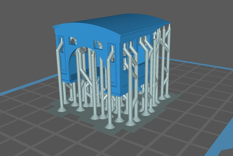
The augmented supports are the outside ones supporting the window opening tops. This was a printing disaster; the roof rear end was tapered toward the middle, and the rear ends of the cab slanted up, and the roof surface had distinct layer lines. The cause of the latter was easy to see, paucity of supports, the former not so much - I would have thought the corner supports would have prevented what happened. So, I stared at the model in the slicer for a bit, then it occurred to me - if I tilted it forward 45 degrees, then added supports along each bottom edge, the rest of the model would support itself, so to speak. If a layer of pixels had no pixel further than 1 pixel from the previous layer, the previous layer would have enough hold on the new pixels to pull them along. Then, the remaining edges needing support would be the top edges of some window openings. Here’s what I ended up with:
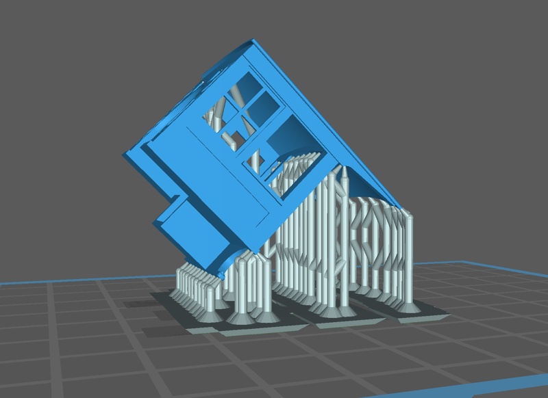
And here’s how it printed:
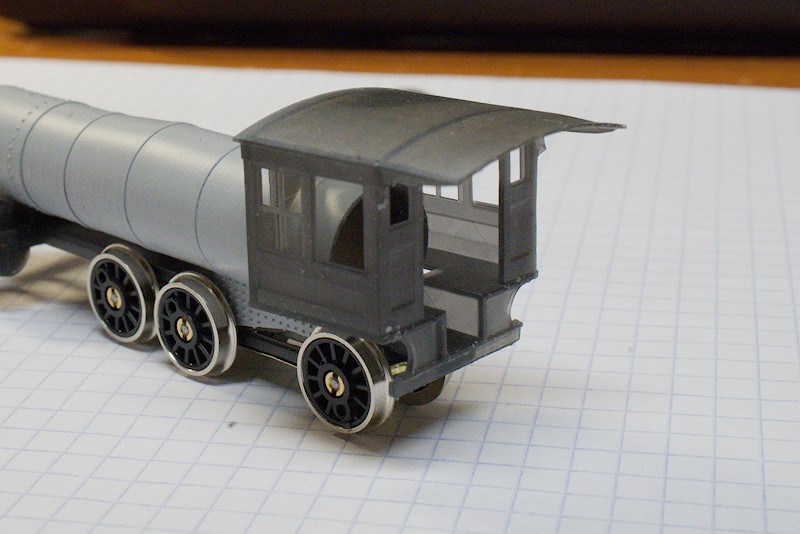
Mostly successful, you might notice the “duckbill” upturn in the cab roof end. For the next print I’ll try moving the support from the end edge to the underside, see if that holds the roof straight. With the exception of that, the print turned out really nice, even the cab roof was nice and smooth, no layer lines. I’m convinced now, a gradually sloping surface needs to be tilted to avoid putting whole regions of surface on the layer lines. Oh, there are some support leavings in the photo, mostly from supports that were close to an edge of the model and got “cured in” with the model. Nothing an Xacto knife can’t take care of…
With the cab, I now have the major parts of the engine structure. Now, my attention can shift to 1) drive train, and 2) decoration. I also need to stop printing for a bit, do some PM on the vat and resin, and a couple of cabinet mods that have become evident in their necessity.
Resources
(Top)