DRG #168's Engine Core
Putting it out there…
After a few iterations of various parts, I finally arrived at a set of six parts that go together to make the core of the #168 engine:
- Frame
- Front-end (cylinders and chests, smokebox cradle, front end beam)
- Smokebox-Boiler-Firebox
- Smokebox front
- Firebox backhead
- Cab
With the exception of the front end, the parts are all agnostic to particular locomotives of the T-12 class, or a particular period. Additionally, I refactored things to make the frame producible in a few different ways, various printing, brass casting, and brass fabrication. They’re held together with two 0-80 screws and nuts, one through the cylinder chest and smokebox (the pilot truck wiil also be attached here) and one through the frame, cab floor tab, and backhead base. Here are a couple of renders of the parts flying in close formation:
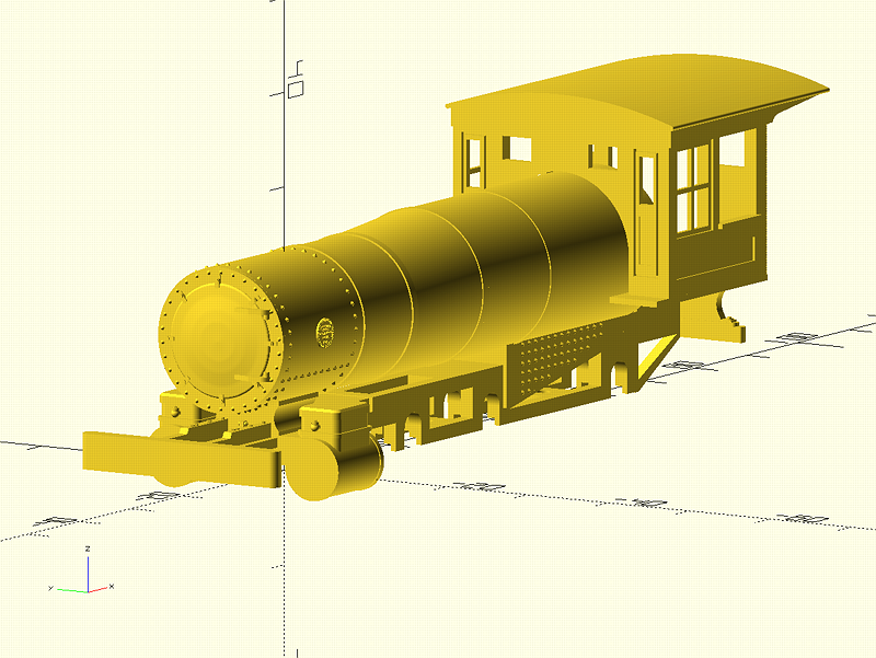
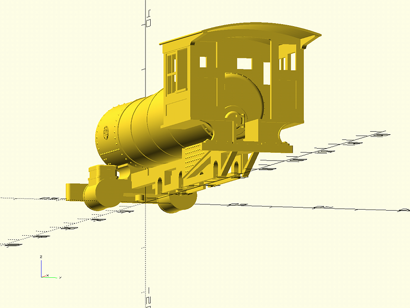
These are actually renders of the .stl files, positioned at their interfaces to each other. OpenSCAD has an import() operator that’ll read a .stl file and present it for further manipulation like any other module. The script to do this was six lines long, one for each import, each prepended with a translate() to move it into the proper position. Looks like this:
import("frame_forprint.stl");
translate([53.6,0,6.3])  import("cab_forprint.stl");
translate([57.9,0,15.5]) import("firebox_backhead_forprint.stl");
translate([-12,0,7.65])  import("smokebox_boiler_firebox_forprint.stl");
translate([-12,0,15.38]) import("smokebox_front_forprint.stl");
translate([-19.06,0,2])  import("frontend_forprint.stl");
I let the frame load with default position of the front end on the XYZ origin, and translated all the other parts around it.
The final print before I declared them done was a bit of a disaster. I printed all six parts in one go, crowding up the build plate almost to capacity. In doing so, I made it rather difficult to fly around and place supports, and I missed a few on the cab and front end. Here’s a picture of it, sitting on a cobbled-together pilot truck and Scalelink drivers:
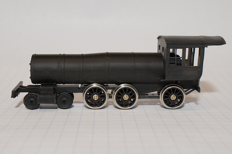
Note the turn-up of the front bolster, and the curved bottom rear end of the cab. I’ve successfully printed these parts before, so I know I just need to be diligent in support placement.
A number of the part iterations were to accommodate changes that support easier assembly. For instance, it was next to impossible to hold the nut in place in the tight spots while snaking and threading the screw, so I modeled nut retainers in the smokebox and backhead base where the nut can be placed and anchored with a bit of CA adhesive. I also included slots and keys for placing the backhead in the cab and the smokebox front in the smokebox. The initial temptation was to just glue things together, but that would not let me replace single parts, such as the resin frame with a brass frame. Also, the backhead as currently modeled is quite basic, and I want to spend quality time decorating it with all the valves, rivets water glasses, etc. Also, if a motor ends up in the firebox, need to be able to access it for maintenance.
The frame is modeled with a slot above the front driver to accommodate the gear drive. That may not eventually prove to be the best driver for driving with the motor, so the location of that slot may change…
Now, there’s also a lot of modeling missing here. Crosshead and yoke, althought there’s a placement slot in the frame for it. Rods, running boards, handrails and stanchions. The whole top-end lineup of headlamp, smokestack, domes, bell, and generator. Various plumbing, including the compressor. All sorts of cab details. Oh, a tender. A lot of this omission is to allow modeling various particular locomotives of the class, as well as different periods. For instance, I left the pilot off because it was a pipe assembly in it’s last version on the DRG, and now it’s wood in the restoration. The running boards and compressor are also in that category as the initial deliveries from Baldwin did not have compressors.
So, I decided to start the Github repository with these parts. You can find them here:
https://github.com/butcherg/DRG_168
This first post consists of the six 3D-printable .STL files and an integration.scad that does the integrated render in OpenSCAD like depicted above. I’m releasing these files for others to use under a Creative Commons license that allows all use, personal and commercial, as long as attribution to the creator is made. I’m not interested in monetizing any aspect of this project, except maybe to post parts at Shapeways with the proceeds going to #168’s maintenance fund, still toying with that idea. I will say, if someone decides to do that with the parts for their personal gain, I’ll probably go ahead with it and compete with them.
I’m going to continue posting .STLs as I create and print parts, so eventually the repository will contain all the parts needed to make a #168 model. I will eventually also post OpenSCAD scripts, but this will be a large endeavor as my code and file organization is a bit of a mess right now. I will continue to post code snippets here as I discuss various approaches to modeling in OpenSCAD.
There’s still a lot of work ahead to make this a complete model. I’m going to proceed with that, documenting my progress here. My first priority is going to be a static model, get all the parts designed, printed, and a couple of copies assembled for my own display and a few gifts. Then, I’ll take one copy, disassemble it, and start work on propulsion.
If you feel so inclined, download the engine core .STLs and give it a go. Or, just render them in OpenSCAD, take dimensions, and pick at my modeling. Those familiar with Github can clone the repository, and pull it periodically to update it. For those not github-familiar, you can download a .zip file with the repository contents at the Releases link in the right-hand columm of the repository web page; the release that is current at the publishing of this post is v0.1.