DRG #168 Decorations, Part 1
Extruding fun, and I dislike glue.
Table of Contents:
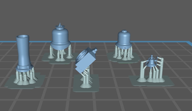
I decided to shift my focus away from propulsion and concentrate on making a static model of DRG #168. Doesn’t mean I’m totally ignoring it, I’m still doing things like cutting sheet brass for side rods and crosshead guides, but I’m spending a lot of evening time cobbling together “decorations”, that is, non-functional items that make it look like a steam locomotive. This post will focus on the “top-line” of the boiler, from the headlamp to the generator. I’ve also posted some of the parts described below as .stl files to the github repository.
Note: The modeling I present is in OpenSCAD, but the operators and their application can be found in just about any competent CAD program
Modeling
(Top)
Creating parts in any CAD program can be a lot of fun, and a good exercise in creative thinking. Some parts are bog-simple, just stacks of carefully placed cylinders and cubes; others a complicated amalgam of extrusions. I’m going to start with domes as an extrusion tutorial, and overview the rest in order of complexity.
Domes
(Top)
The first parts I modeled for #168 were the steam and sand domes, about 6 months ago. I did this in response to watching a video of a fly cutter in a lathe, cutting the negative curve out of the bottom of a brass dome. If you haven’t seen it before, a fly cutter is mounted to the lathe center, the spinning thing, and the material is mounted in the tool holder. On each revolution, the fly cutter takes a bite out of the static material. A number of things about that; one was the expense of a lathe, but on top of that was what it would take to learn the ins and outs of fly cutting just to make a couple of negative curves. That’s when I decided to pick at 3D printing…
With OpenSCAD, my original dome models were cobbled together from a series of cylinders hulled together, good approximations but there were glaring artifacts of the limitations of this approach. This need is what drove me to learn extrusion, which turns out is really one of the essential mechanisms to model steam locomotives. These beasts are a collection of curve-shaped parts flying in close formation, so a lot of extrusion is needed to make hay in modeling them. If you’re not familiar with the operation, it’s essentially the software equivalent of squirting cookies out of one of those tubes with a cookie pattern on the end. In the CAD program, it’s done by making a two-dimensional shape that describes the profile, then using whatever extrude operation to take that shape and turn it into a three-dimensional object by stacking together layers of the shape until it reaches the height you want.
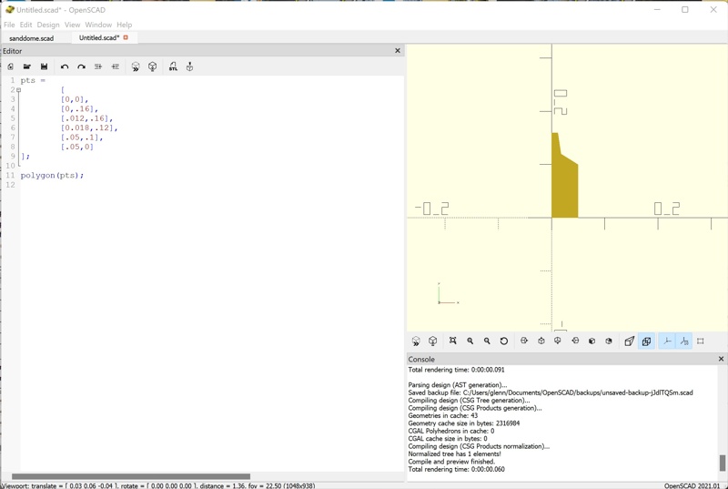
Here’s how the dome base is modeled with extrusion. First, a polygon is defined in the shape of the profile of the base. In OpenSCAD, a polygon is defined as an array of points; here are those points and a plot of them as a polygon so you can see the profile:
Hmmm, not very curvy, is it. In order to do that, I’m going to make use of a very, very useful OpenSCAD library I found early in this endeavor, Round-Anything. I’ll describe where and how to get/install it at the end of the post, but for right now we’ll use it to put some curves in the profile. First, we add a third value to each X-Y point in the point array defining the radius to be made at that point. Then, we use the polyRound() function in the Round-Anything library to add points to the array corresponding to the curve. Here’s what that looks like:
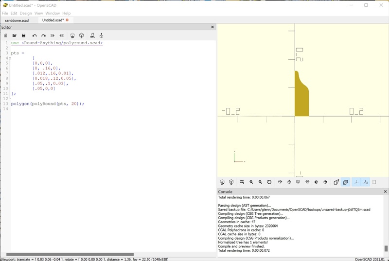
Better, no? Okay bit of explanation - first, the library has to be included so it can be used, hence the ‘use’ statement at the top of the script. Then, the pts array is passed to polyRound(), which returns the modified point array, adding the points needed to define the corners with the appropriate radius. polyRound() returns an X-Y array of points, and the OpenSCAD language lets us use the result of polyRound() by inserting it where we want the array, so we just put the polyRound() call in the polygon() call where point array would go to see the result. Now, make sure you add the radii to all the points in the original array, including 0 to points that don’t “get bent”, or polyRound() will complain loudly and for a long time in error messages.
Okay, with that profile we can now extrude the dome base. OpenSCAD has two extrude operations, linear_extrude() and rotate_extrude(). linear_extrude() behaves pretty much how you’d think, it pulls a three-dimensonal part straight up out of the profile for the distance you specify, but that’s not what we need. rotate_extrude does what we need to make a round dome base:
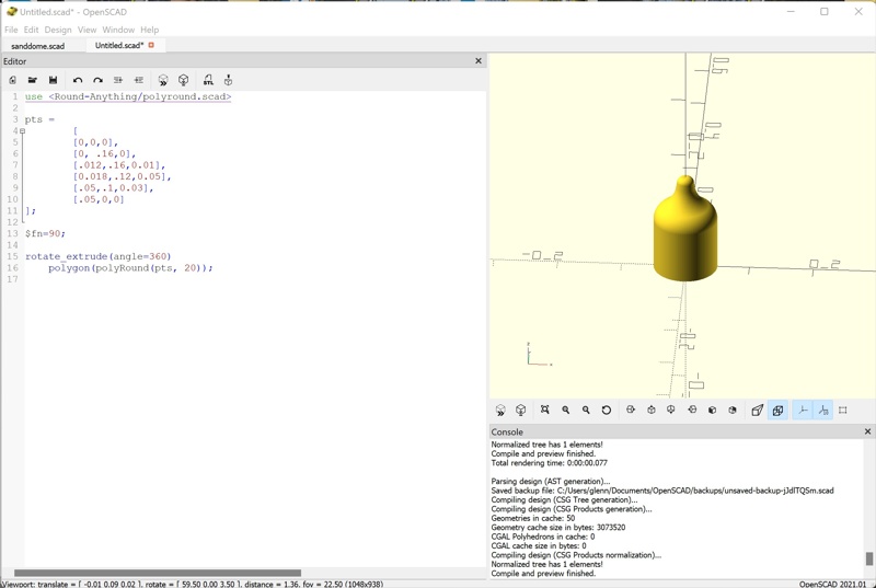
It’s not completely clear how rotate_extrude() works from the screenshot, so let me explain. First, it takes the profile laying flat in the X-Y plane and stands it up so its Y axis is now on the Z axis. Then, it extrudes it around the Z axis for the number of degrees you specify. And, there y’go. Now, this doesn’t look exactly like the dome base; indeed, what we defined was the profile around the dome edge. So, to make that happen, we translate the profile out on the X axis like this:
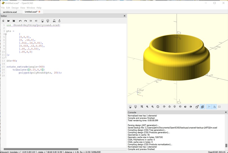
There, now it looks like a dome base. Note the syntax, polygon() under translate() under rotate_extrude(). Those could be all on one line; the separate lines and indentation makes it easier to read. The “innermost” thing is done first, rotate_extrude(), then the result of that is translate()-ed, then the result of that is rotate_extrude()-ed. That’s one of the really powerful things about the OpenSCAD language; any number of operations can be grouped and modified en-masse. More on that later…
The other thing I want to show here is how to get the negative curve in the base that required the fly cutter in metalworking. OpenSCAD has an operator that can subtract one shape from another, difference(). To make the base curved to fit the boiler, we simply subtract a shape sized similarly to the boiler from the dome base, like this:
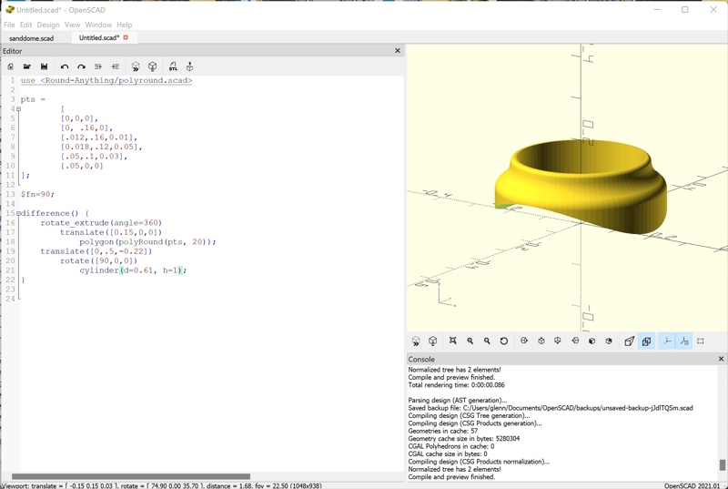
A lot easier than fly-cutting, no? The difference() operator takes two objects in between braces: 1) the object to be rendered, and 2) the object to be subtracted from the rendered object. The cylinder diameter is the diameter of the boiler where the dome will sit. When a cylinder is defined, it is rendered vertically, so it has to be rotated to horizontal. Finally, it has to be translated to intersect with the dome base so it subtracts the proper amount.
Of note, this is a subtractive operation; folk make note of 3D printing as “additive manufacturing”, but really the need for subtraction is just moved into the CAD software. Silly semantics…
Here’s what the subtracted object looks like; OpenSCAD has a view option that makes subtracted parts visible:
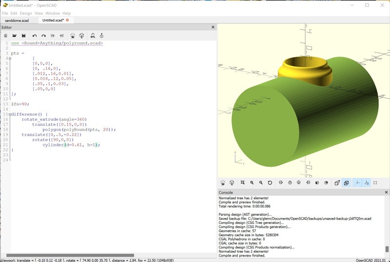
Note that the subtracted object size doesn’t matter in the dimensions that don’t touch the object being modified; I chose 1 for the cylinder height for simplicity.
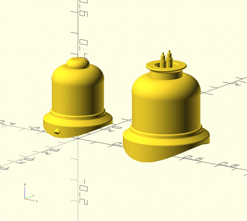
The rest of the dome is a cylinder translated into the dome base, and another extruded shape to make the cap. Here are both the sand and steam domes:
Smokestack
(Top)
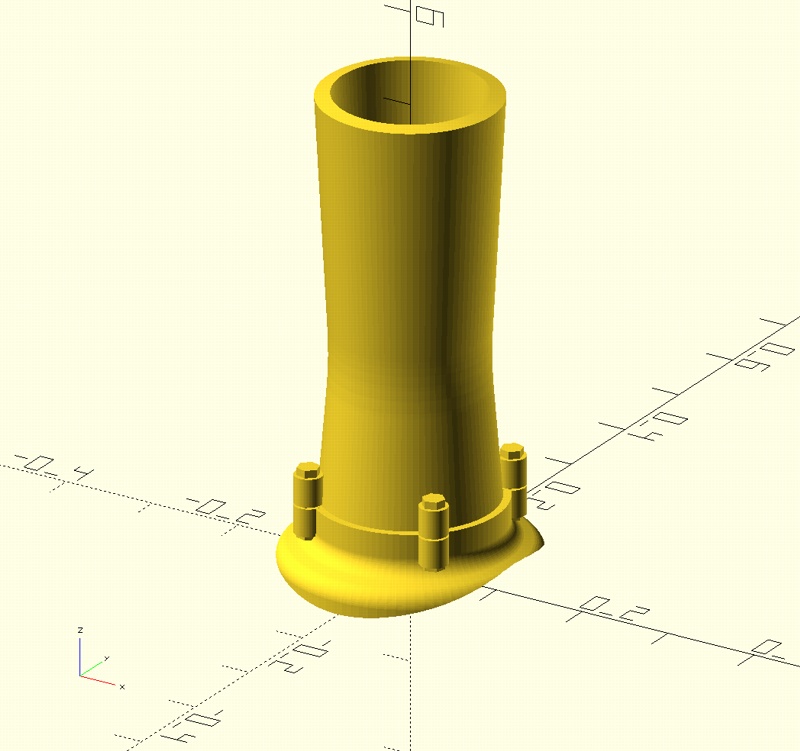
The smokestack was made similarly, except the stack itself is an extrusion. Note the stack is hollow; I could have made the extrusion solid and subtract a cylinder from the center, but I chose to include the void in the point array. The base is just a bit bigger than the stack to make a visible joint, and the four attachment tabs are just cylinders embedded in the stack with a six-sided cyliner embedded in both to make the bolt heads.
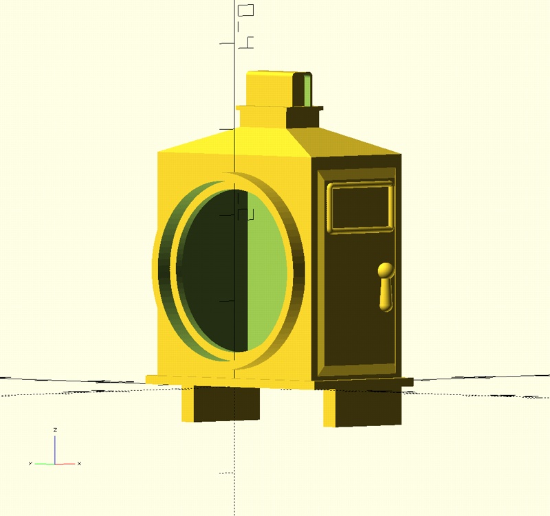
Headlamp
(Top)
The headlamp is a bit more complicated. The main body is hollowed by subtracting a cube, and the port is a subtraction of a cylinder. Both were done in the same difference() operation; in the braces, the first object is the model, and the rest of the objects are subtracted from the first one. The crown is make from a hull() of two cubes to make the sloped surfaces, with other cubes to shape the top. The top shape is a rounded_box() module I wrote to make the cylinder chests; I take such modules and put them in a utilities.scad file just for such reuse. The handle on the side door was simply a cone and two spheres. The number plates on either side are made with another module I wrote called rope_rectangle(), written originally to make the footboards.
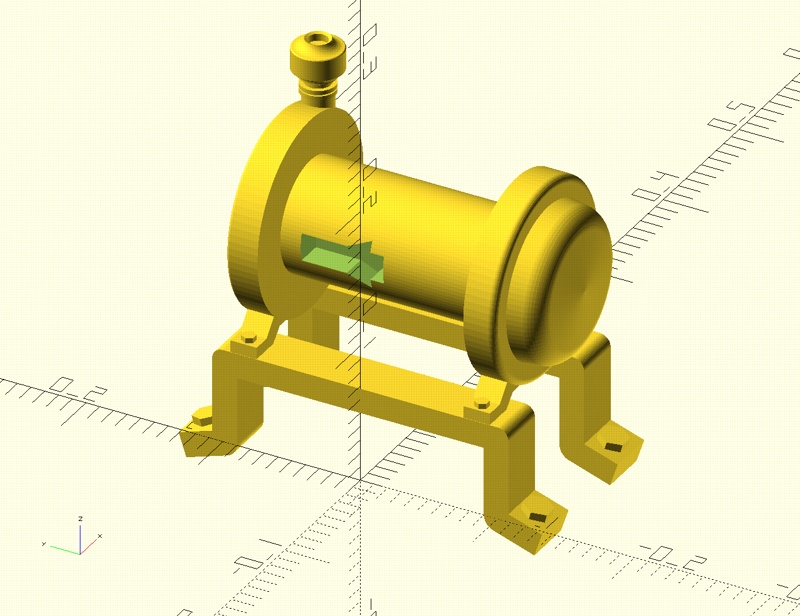
Generator
(Top)
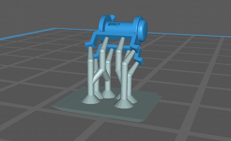
The generator is even more complicated. The prototype is mounted on a bracket made from two bent steel bars; to model that I used another module from Round-Anything, beamChain(). It takes an array of points that describe a path, and makes a rectangular beam along them. I also used polyRound() on that path point array to make the rounded corners. The two end caps and the exhaust stack cap are all rotate_extrude()-ed. The cavity in the central cylinder is a subtraction of a regular cube and an extruded triangle I wrote as a module for utilities.scad. The easy parts were the bolt heads, just six-sided cylinders:
Bell and Hangar
(Top)
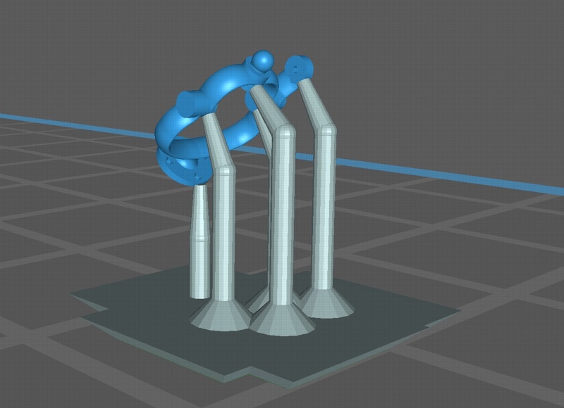
The bell was fairly easy; the hangar was extremely complicated. The bell is just a simple rotate_extrude() of a nice bell profile. The hangar, however is the dictionary picture for the word “ornamental”; here’s a picture of the prototype:
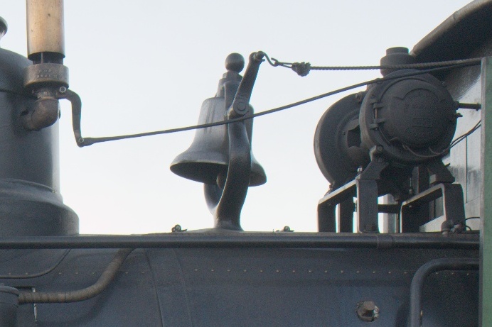
The cradle and yoke are continuously-changing shapes with a somewhat-elliptical profile. It begs using a path extrusion of some sort, so I went looking for that. I did find a path_extrude() module for OpenSCAD, posted in Thingiverse, but the initial results weren’t that great. So, I broke down and downloaded Blender. I’d used it before to make models for 3D virtual environments, didn’t think the re-learning curve would be that great. Bad assumption, after some digging I found the appropriate extrusion operator, but I just timed-out with all the keystroke combinations and other things I had to figure out. Back to path_extrude(), similar tedious challenges, but it felt more reasonable to my odd way of thinking.
The model I have so far looks like this:
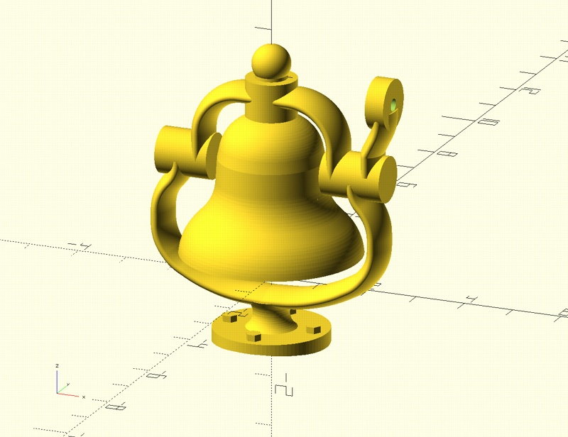
The real bell is a little taller, and the cradle tapers as it reaches the yoke, but this represents a significant effort at integrating tools that don’t know about each other to approximate the needed shapes. I essentially defined point arrays for the shape profile, cradle and yoke paths, then fed them to polyRound() to round them out. path_extrude needs 3D path, that is, path points need to be X,Y,Z coordinates, and polyRound() only provides X and Y, so I had to write a function to add 0 back to each point. That was a significant head-hurter, as it wasn’t intuitively obvious how OpenSCAD syntax would do that. Here’s the function:
//used with path_extrude to make paths that have been rounded with polyRound():
function addnum(v, n) =
		[for (i = v) concat(i, n)];
in case one finds a convoluted need for it… :D
Definitely still a work-in-progress…
Fabrication
(Top)
Probably more influenced by the traditional factoring of these parts, that is, bought as separate castings from Precision Scale Models, I first pursued printing these parts separately for mounting. I applied supports manually using what I’d learned from the cab and boiler, printing circular parts “straight-up”, tilting parts with rectangular shapes 45 degrees to minimize layer exposure for flat surfaces and taking advantage of the model to “self-support” at angled lines. The domes and smokestack required compromise; I wanted to maintain nice details in the structures, but also needed precision in the boiler interface negative curve. I figured the negative curves would probably need some sanding anyway, so I put the supports there. Here’s the first round of parts:
Note how tiny/tiny is the bell and hangar. I did three iterations of the hangar, upping the profile dimensions a bit until it was big enough to handle.
On parts this small, it was hard to remove supports without damaging the part. For a subsequent iteration of the bell hangar, I decided to break my rule of cherished surfaces and put the supports all on one side:
This made it easier to cut them flush using the printer-supplied cutters. Here’s where I ended up:
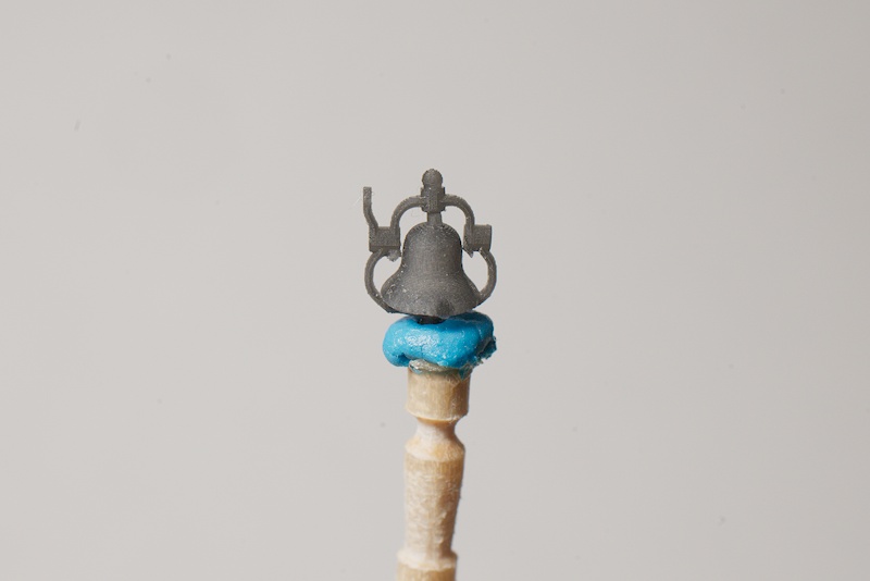
This one is blemished from support removal, indeed, there’s still support stuff on the model I was too chicken to carve off. The hangar and bell are separate parts now, so the bell can be painted separate from the hangar.
The domes and stack required some sanding to remove all vestiges of support from the bottoms, but the interface was still compromised from the curves induced between the supports. This is something I’ve noticed in most models where I I had a flat surface aligned with a starting layer. A lot of advice would be to support the crap out of it, but I’ve found rotating 45 degrees turns the flat surfaces away from being islands in favor of edges, which tolerate being the first layer better. I hope I’m explaining this well enough; it’s turned into being a foundational concept of scale model printing for me…
The generator was pretty straightforward to support:
I mounted the parts to my test article with CA glue:
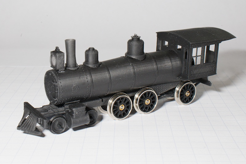
I hadn’t glued a model in more than 30 years, found myself wanting to “styrene-weld” with CA, not the best idea. Also, the uneven boiler interfaces show, for next such mounting I’m going to get some sanding film to wrap around the boiler and sand the parts’ negative curves.
But then, I got to thinking about the whole integration process and what I’ve learned about printing, in the next few weeks I’m going to print the boiler with the three curved-interface parts integrated. No support shenanigans, no glue surgery. To do that, I’m going to assemble the parts with their .stl files:
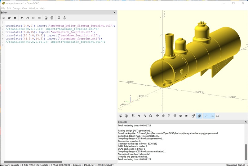
It’s rather easy to do this with OpenSCAD; it has an import() operation that reads in .stl files. The side benefit of this way of integrating is that there’s no parsing and processing of OpenSCAD operators to render, which makes exporting the amalgam to another .stl an order of magnitude faster.
Note that the headlamp and generator are in the script, but commented out. I imported the amalgam to the slicer to try supports, and I found that these parts had island edges that I couldn’t easily support. That, and those parts are a bit easier to glue properly, so I concentrated on the curved-interface parts.
I’m going to continue designing and printing parts to make a fully 3D-printed, static model. Once I have that, I’ll then divert attention to designing and fabricating a drive mechanism.
Resources
(Top)
- As of this date, I’ve added the headlamp, smokestack, sand dome, steam dome, and generator to the github repo: https://github.com/butcherg/DRG_168
- Round-Anything, https://github.com/Irev-Dev/Round-Anything. You can clone the repository, or go to Releases and download the .zip file, or you can just retrieve polyround.scad directly from the top-level directory of the Github repository. However you retrieve it, put polyround.scad in the OpenSCAD libraries directory, for Windows, it’s OpenSCAD/libraries/ in your Documents directory; for Linux, it’s .local/share/OpenSCAD/libraries/ in your home directory.
- path_extrude, https://www.thingiverse.com/thing:186660. Same thing as with polyround.scad, put path_extrude.scad in your libraries directory.