Part Integration Workflow
Right tools for the job…
Table of Contents:
Quite a bit of time has passed from the last post; wine cellar construction, then retirement transition interrupted my work on #168. However, in the interregnum I did a lot of thinking about workflow, and the high bar of CAD for most modelers. I’ve posted a bit about my OpenSCAD work in some of the model railroading forums, and I get a few “that’s interesting” comments, but not much else. Don’t blame ’em, OpenSCAD is rough-going for anyone with no prior programming experience.
Anticipating getting back to printing soon, I pulled together all the .stl files I wanted to print for my next iteration of #168. I needed to re-integrate the boiler assembly with the smokestack, domes, and footboards, so I dug out the OpenSCAD files I made for that purpose, and proceeded to struggle with re-creating the assembly. Mesh errors, long rendering times at $fn=360 (number of faces in cylinders and other round objects), led me to reconsider the whole integration thing I described in the previous post. Before I abandoned the idea, I set out to find other tools that might be more suitable.
I had already downloaded a few “mesh” programs, designed mainly to fix various mesh issues. I was headed toward Blender, but I decided to first try using one of those programs to load .stl files, move them into position, and save a single mesh of the amalgam. Here I’ll describe using each, with its good and bad points.
Coordinates
Before we get into using the programs, a bit about coordinates. In any CAD program, locations in the space where parts are worked with is mapped out with a coordinate system. Pretty much like the X-Y graphs you learned in high school, the X and Y axes meet at a place called the origin. Each axis is a number line, and a spot on the graph has two numbers that describe its location on each of the X and Y axes. To expand that concept to three dimensions, a third axis is added coming out of the origin perpendicular to the other two axes. This third axis is named Z, go figure. Now, there’s no gravity in this space, so any of the three axes could be “up”. However, the convention is to use Z as “up”. Now, we’re not going to worry about specific coordinates in this post, just that moving things around involves changing those three numbers.
So, as you do these tasks for the post, we’re going to recognize the Z axis as up. Also, we’re going to recognize the X axis as the tram line of the model, that is, the line running from front to back. That leaves Y to describe lateral, or side-to-side movement.
Autodesk MeshMixer
(Top)
First thing of note about this program, in September 2021 Autodesk announced end-of-life for it, as all the relevant functionality had been incorporated into Fusion 360. So, while it appears one can use Fusion 360 for mesh integration, I’m not going to report on it. As of today, Meshmixer is still available for free download, link in the Resources section below. It’s only available for Windows, not an issue for most of you, but I use both Windows and Ubuntu Linux so I want to be able to use the same tools on both computers.
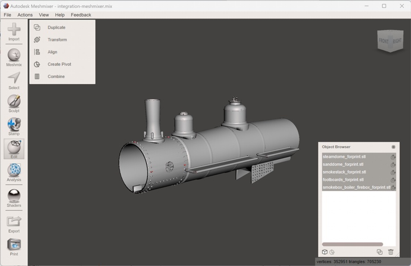
I used my #168 boiler integration to test the functionality, importing the smokebox-boiler-firebox.stl and then importing and moving the smokestack.stl, sanddome.stl, steamdome.stl, and footboards.stl into the window. As I did the imports, the filenames were added to the Object Browser subwindow, more on that in a minute. Meshmixer deposits each import at the origin of the three axes, so the objects are all lined up in the X direction. Moving the objects was easy enough, the object can be selected either by clicking the object in the window or its file name in the Object Browser, then selecting Edit in the toolbar and then the Transform tool. This puts a “translate axis” on the object, three arrows that point in each of the X, Y and Z directions that you can drag to move the object in the associated direction. Dragging the object up to the boiler top on the Z axis, then back along the top on the X axis to the desired position was trivial, then up and down along the Z axis to set it on the top of the boiler (more about this later). When done with these movements, select “Accept” in the tool box to “bake in” the movement, that is, actually change the mesh’s coordinates to the new positions.
Import and place all the .stl files, then save the project with the File -> Save menu item. This is important; you want to save the project file with the separate objects before you do the next step. To make the combined mesh, start by selecting all the objects in the Object Browser by holding down the Ctrl key and clicking each one. As you do this, the toolbar on the left automatically brings up the available operators, and the last one in the list is “Combine”. Click on that operator, and Meshmixer will combine the entire mesh list into the first mesh. That’s why you save the project before doing the Combine, it’s a “destructive” operation. Here’s a screenshot just before the combine operation:
Now, click the Export tool in the tool bar, select an approprate name for the .stl file (the first .stl in the Object Browser will probably be in that box, change it or you’ll save over that file), and make sure the Binary STL file type is selected. Click Save, and you now have a consolidated mesh file for printing.
Meshlab
(Top)
This is an open-source equivalent to Meshmixer, source code available under the GPL 3.0 license. You don’t have to go there, however; installers for Windows and MacOS are available at their website. I installed it on my Ubuntu desktop with sudo apt install meshlab. As of this date it’s still in active development, last commit to the source tree was 5 days ago.
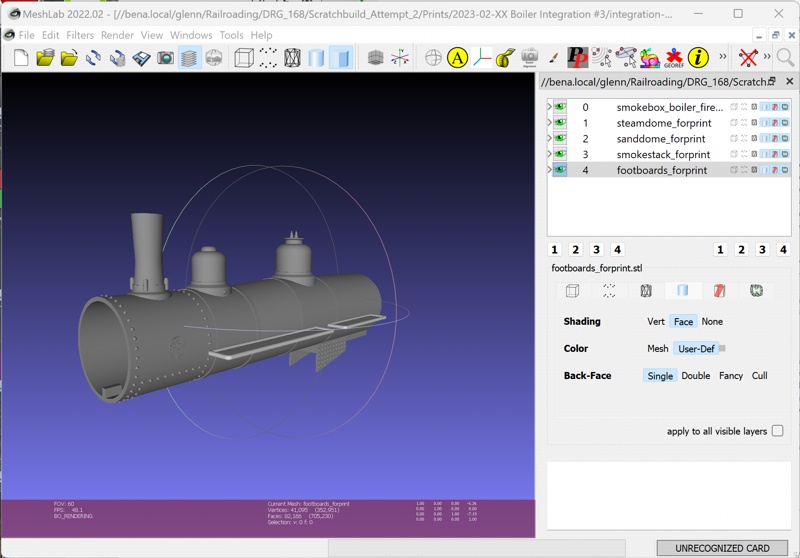
I performed the same integration exercise using Meshlab. The meshes are imported using the menu, File -> Import Mesh. To move the other meshes in Meshlab is a bit more involved, you have to 1) select it in the object list in the right-hand pane, 2) click the Manipulators tool in the toolbar or selecting Edit -> Manipulators Tool in the menu. When you do that, a little pane will appear in the top-left of the main window that tells you what to do. 3) click the mouse on the object itself, then 4) Type “T”, for Translate, then “Z” for the Z axis. Now, you can drag the object up and down in the Z direction. Place it at the top of the boiler, then press “Return” to bake in the movement. Rinse and repeat to move it back on the boiler, then again to place the object on the boiler (more on this later). Geesh…
Same as with Meshmixer, import and place all the .stl files, then save the project with File -> Save Project As. Once that’s done, combine the meshes with the menu selection Filters -> Mesh Layer -> Flatten Visible Layers. Click Apply in the dialog, then Close. You’ll now see a single mesh in the object list, called Merged Mesh. Export it with the menu, File -> Export As. You’ll have to select the STL file type; Meshlab will save either ASCII or binary STLs, selectable in the program properties. It seems to save either type equally well. Here’s a screenshot of Meshlab just before the meshes are flattened:
(Update) Microsoft 3DBuilder
(Top)
I hate to post this one… :D
Looking around the apps that came with my Surface 7 tablet, found 3DBuilder. Well, what the heck, let’s try the integration exercise, not really expecting any success. I was wrong…
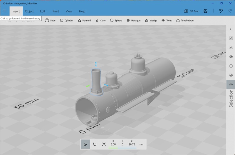
It opened each mesh without fuss, except some .stl files required specifying the measurement unit. When each model was added, the program would go over it and, if it found problems, it would ask to fix them. For this exercise, the boiler assembly and domes required such, went a bit slowly on my tablet, but resulted in models that weren’t deformed (forgot to point out, MeshMixer did introduce some deformation doing the same thing). After adding each model, the model was selected and the move arrows were presented, so I moved each object up to the top of the boiler and then back to its proper position. Of note was that precise placement with the model embedded just slightly in the boiler was the easiest with 3DBuilder vice the others; when I zoomed into the model edge, the movement arrows were kept in view.
After model placement, I just saved the whole thing as a .stl file. Afterward, I noticed there was a merge function, but I didn’t try that. As far as I know, 3DBuilder just saved a single .stl file with the three meshes glommed together. I loaded that mesh into the slicer and sliced it; the whole thing presented as one integral model.
So, success with 3DBuilder. In fact, it was the easiest of the three programs to use. Also, it presented objects and operators that would allow building of simple structures to which .stl files of things like windows, doors, and siding could be added to make structure walls.
3DBuilder is not open-source software, poo. However, it’s free with any Windows 11 install, making it the very easiest program to get a hold of. And, I have to say, a very easy thing to use to integrate model parts for integrated printing.
Object Placement
(Top)
Probably wondering about “(more about this later)”, well here ’tis. When you combine two meshes for printing, they need to form one integral object. To do this, you need to embed the moved object into the other object by a small amount. It can be hard sometimes to tell from the program window that this embed is present; of the two programs, Meshlab render seems to show it best. However, the real test is done in the slicer; load the mesh in the slicer program, slice it, then use the slider to show a layer where the two parts meet. If there’s a gap between the two, the un-supported part won’t be attached to the main part,and will print as a single layer stuck to the FEP in a resin printer. See the previous post for a poignant example of such. For the model we’ve been integrating in this post, here’s what it looks like in the Chitubox slicer:
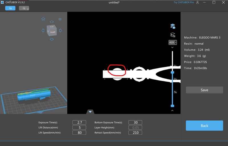
The smokestack gap is circled in red; compare that to the sanddome next to it, which has no such gap between it and the boiler. With both programs, I iterated through mesh combine/flatten, export to stl, load in slicer and slice, then go back to the mesh program to make adjustments and repeat.
More Ruminations
(Top)
So, while I plan to use Meshlab for my mesh integration adventures, I recommend Meshmixer to others for the easier interface. Fusion 360 may be another one to consider; easy entry into mesh integration, while having a full-featured CAD tool to expand into.
CAD-ing parts from scratch is not easy, in any program. But, I think this demostration shows an intermediate level of engagement where one can download parts and integrate them into complete models for printing. The boiler demonstration is a bit simplistic, just pushing parts together, and I have a few other ideas related to structure fabrication. I’ll get to them in a subsequent post.
Resources
(Top)
- https://meshmixer.com/download.html, download site for Meshmixer.
- https://www.meshlab.net/#download, download site for Meshlab.
- https://www.thingiverse.com/thing:5690155, double-hung window at Thingiverse.