Finishing the Engine
Running out of black resin…
Table of Contents:
Quite a bit of time has passed from the last post (Geesh, I used the same line last time…). Funny, now that I’m retired I have a lot more time to do modeling, but less time to do blog posts. Anyway, as of today I pretty much have the complete engine modeled and about 95% of it printed at least once. So the activity is now about integration, getting it all to fit easily. I’m aiming to have a complete print of the engine before I run out of black resin; fortunately, all of the large parts are printed, so I can concentrate on things like the rods and front end. This post will be about discoveries and insights gained in the past few months, and a picture of the almost-complete engine. I’ve got the tender about 80% modeled, but no prints yet; will get back to that after I have a printed instance of the engine in front of me (in black :D )…
The Model
(Top)
Here’s a render of all the parts I’ve modeled to date, flying in close formation :D
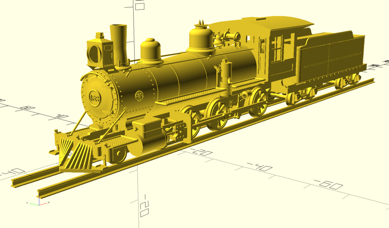
This is a render of the stl_integration.scad file in the stl/ directory of the github repo. That file has been really helpful in pulling the whole model together, providing a place to play the actual .stl mesh files as they’re supposed to be fit together. Doing so, you find things, such as “Hmmm… the footboards are too long, pushing into the cab.” I’m finding that using two references for measurements, the #169 drawing and the measurement photos I’ve taken, will sometimes give conflicting results that manifest in fit inconsistencies. Starting over, I’d pick one drawing or overall photograph from which to take reference measurements.
Originally, stl_integration.scad just contained a list of import statements to pull in all the .stl files, translated to their appropriate places. But recently I’ve started to include non-printed parts for alignment purposes, e.g., handrails. Handrails will be wire, but I modeled them in the integration file to use as alignment references for placing the stanchions. Another is the brass frame spine, which I’ll describe later.
One thing I’ve removed from the integration file are the translate coordinates for the .stl files. They’re all defined as variables in globals.scad, located in the lib/ directory. I decided to do that when I spent about a half an hour scooching things around in the front end, smokebox, and frame models moving the screw hole in which they all participate. globals.scad contains all the coordinates of the models in inches, as well as the X coordinates of the screw holes; the respective front end, smokebox, and frame scripts use these coordinates to 1) translate themselves to the integration coordinates, 2) difference() them with screwhole cylinders translated to the screwhole coordinates, and 3) translate themselves back to their origin position for printing. Now, if I move a screw hole, all the participating models just drill themselves in the correct position.
Another use of globals.scad translate coordinates is for a model to include an adjacent model for positioning of components. Such code is used while I scooch translate() coordinates around, and then commented out for the committed version of the script.
scadmake
(Top)
As I iteratively modified parts and render them to .stl for print, I began to search for ways to streamline the workflow. One way was to start using the command-line invocation of OpenSCAD to generate the .stl files, and being a programmer it only made sense for me to use a Makefile with the make program. For non-programmers, make is a unix program used by a lot of programming projects to manage the compiling of their code bases into executables and/or libraries. The key thing of make is that it tracks file modification times and only compiles code that has changed, saving sometimes hours of time in avoiding compiling things that didn’t change.
OpenSCAD scripts work like most other programming languages in this regard, and the command-line invocation of openscad helps to solidify that consistency. But OpenSCAD is a bit different in that a object file (stl) is not generated for scripts that are included or used by other scripts, which confounds make just a bit. OpenSCAD actually has a couple of command-line switches to facilitate Makefiles, but I found them to be non-responsive to my particular organization of the project. So, I decided one day to try writing a make equivalent for .scad scripts. After about two days of programming, I had scadmake, a C++ program that reads all the scripts in a directory to find their use and include statements, then use that information to figure out which .scad files need to be re-run to generate their associated .stl mesh files. Been using it for a few weeks now, works like a treat. It uses a configuration file that is much simpler than make; I’ll add an example SCADMakefile to the repository.
A link to the SCADMake github repository is in the Resources section at the bottom of the post. It’s only available in source-code form at this time; the program is pretty simple to compile and only needs a very recent version of GNU C++, no other dependencies. I’ve compiled it in Ubuntu Linux and Windows using MSYS2.
The Resin Medium
(Top)
After I determined an operating version of #168 would require metal mechanical parts, I set out to first make a static model completely out of resin-printed parts. However, as I got to integrating more parts I began to identify other shortcomings of the medium. The most pronounced one was the linear integrity of the frame, it just wouldn’t sit straight due to small dimensions around the driver slots. This caused the front end to droop considerably. What I decided to do was to modify the frame to be two parts: 1) a brass “spine”, and a resin-printed component with the driver slots and some modeling detail:
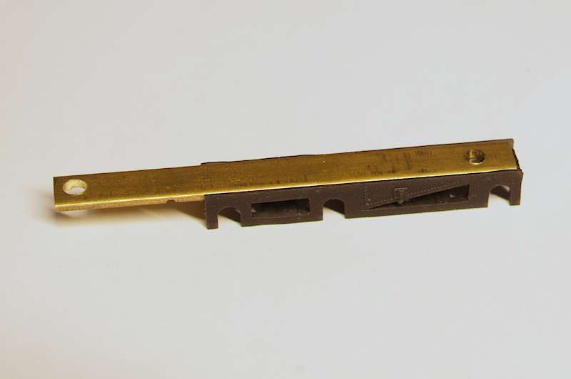
The spine is a segment of K&S brass strip, 1/4" x 1/16", cut to 2.675" length. The resin component has a slot in its top that provides a snug fit for the spine, registered to the back end. The two holes allow the assembly screws to pass. The front end assembly has a slot in the cylinder chest into which the spine slides, along with a slot in the crosshead guide hangar to allow the spine to pass. The engine definitely takes on a “straight” posture with this frame design:
As I modeled, I strived to make parts that were close to prototype dimensions. As I printed, I found sometimes that those dimensions presented structural integrity issues. The handrail stanchions were the first; I lost a few of them in the alcohol wash before I added a couple of thou to all the dimensions. They’re still fragile, but now I’ve moved the propensity to scrape them off to my subsequent man-handling. Same with the cut lever supports and pilot footplates. These parts now look a bit cartoonish in CAD, but I think such is just part of the compromises maded in scale modeling.
Printing Management
(Top)
As I started to collect finished parts, got to thinking about how to organize the printing workflow. One thing that I wanted to capture was support placement; I don’t use the auto tools in my slicing program, so I have to manually place supports every time I generate a new mesh file. I’m less concerned with the tedium of that than with missing a support I’d previously determined to solve a particular problem. So, here’s what I came up with to organize printing.
Chitubox project files have an interesting capability of which I took advantage, you can create a project file and then add other project files to it. There you go, make a project file for each part, and then organize printing around collections of particular parts. So, I made a Parts/ directory, into which I put a Chitubox .project file for each part in the github scad/ directory. Every time one of the .scad files is modified, I generate a new .stl file and then update the .chitubox file in Parts/ to use the new .stl file. Then, when I want to print a collection of parts, I start a new .chitubox project file and add to it the relevant Parts/*.chitubox files. Here’s a screenshot of such a project file:
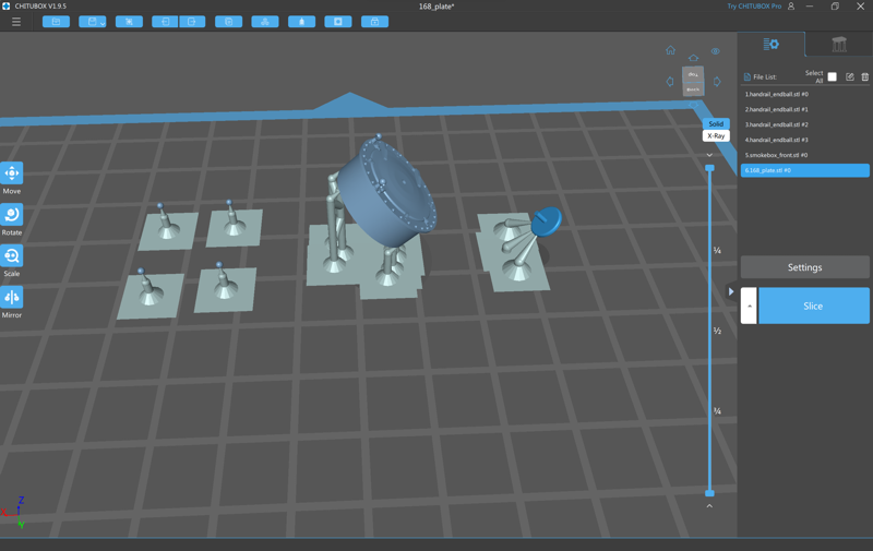
Left-to-right: 1) four handrail end caps, 2) smokebox front, and 3) front number plate. For the end caps, I added the end cap project file which contained a single cap, and cloned it three times in Chitubox.
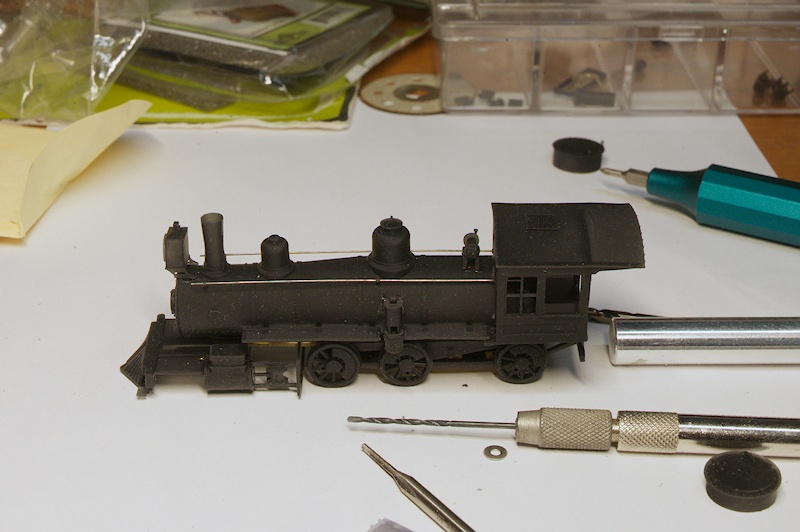
As I finish the engine parts I have enough to build the engine core, so that assembly of parts currently (10/29/2023) sits on my bench. With that, I print individual parts and add them to the assembly, or in come cases I print a part, add it to the assembly, find out some aspect of it doesn’t work, change the .scad, generate the .stl, update the .chitubox, and print it again, usually with other parts in various stages of maturity. Having the Parts/ directory of parts makes assembling a “build plate” of such a lot easier.
I’m not going to add this stage of the workflow to the Github repository. First, it’s Elegoo-specific, so it’d only support a fraction of users. But more importantly, I’m seeing the printing process as being highly individual - some may go at it like I have, others might just ship the .stl collection to Shapeways. Me, I envision having a small collection of variations: static, running, various levels of detail, etc. For some of those there may be parts that I model for my own satisfaction, and not share publicly. What I want the Github repository to be is a starting point, one that mainly lowers the CAD bar. Definitely a “craftsman” kit…
Next Steps
(Top)
Right now, I’ve got a few more parts to print to finish this initial iteration of the engine. I’m also having fun with wire, making handrails, cut levers, and piping. Some of that work will take a bit, as I’m getting some tools for Christmas that I need. S’okay, need to work on the tender - got the major parts CADded, need to work on things like the air tank, ladder, rear cut lever. Also need to add some material to the cistern bottom to keep the walls from warping in printing. I’ve had a goal to get the first iteration of the locomotive printed in black resin, which is looking to happen right where I run out. So, the initial tender is going to be gray.
Also, I’m assembling the parts and materials to make an airbrush spray booth. My neighbor gifted me his airbrush setup, double-action Masters, small compressor, and all the accessories, thanks Rich! I’m building the spray booth to use the printing cabinet exhaust system. And, got a stock of Micromark sanding foams to start working on finishes; 0.05mm layer height in resin still leaves noticeable layers, and I particularly want a smooth finish on the boiler to bring out the shininess of the stainless steel Stathi used on the restoration.
And, I’m also starting to think through the operating version. I may at some point investigate more exotic resins for mechanical parts, but for the first operating model I’m going to fall back to what I’ve envisioned for some time - doing this in brass. Just procured a Sherline lathe and mill column, deserves a post by itself. I think now I’m more ready to take on learning machining, and add those skills to my modeling inventory. And, there’s a wider body of knowledge out there regarding brass mechanisms. I’ve slogged through enough discovery for the time being, time to fall back to learning tried-and-true…
Resources
(Top)
-https://github.com/butcherg/SCADMake: Github repository for the scadmake program.